Week 11: Output devices
Download this week's code
Assignment requirements
The first checklist
- Add an output device to a microcontroller board you've designed and program it to do something
The second checklist: Learning outcomes
- Demonstrate workflows used in circuit board design and fabrication
- Implement and interpret programming protocols
The third checklist: Have you…
- Described your design and fabrication process using words/images/screenshots.
- Explained the programming process/es you used and how the microcontroller datasheet helped you.
- Outlined problems and how you fixed them
- Included original design files and code
Intro
First, think about what I want to do for the final project. Performing a 3D printer. Emma suggested that I should make one axis of a 3D printer. I don't want to do that, but since it's the printer's motors making the noise, maybe I should at least work with the motors a little to understand how they work.
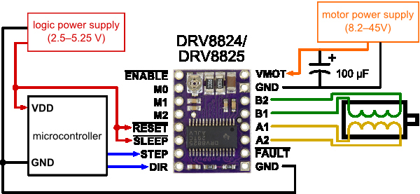
What kinds of motors do they use? Bipolar stepper motors. Emma has provided me the motor to use. The motor driver is the DRV8825. Information here. Chip datasheet here. And I should use a 100uF capacitor, capacitor datasheet here. And the motor I will use is the SY42STH38-1684A, motor information here, motor datasheet here.
First I read all the information and all the datasheets. This page gave me some good information about stepper motors and their characteristics, and it also mentions the same driver board that I'm using.
Motor information:
- Step angle: 1.8°. This means 200 steps.
- Rated voltage: 2.8V. This will be controlled by the trimpot on the motor driver.
- Rated current: 1.68A (that's a lot!) If I see more coming from the power supply then something is wrong.
- There are force and torque ratings that don't matter for my application, but probably would if I was doing something practical.
Capacitor information:
- It has a polarity! The black stripe on the packaging is the negative terminal.
- Farnell says the case diameter is 10 mm, this will matter if I'm making a part for it in Eagle.
Stepper driver carrier:
- According to the dimensions diagram, the space between the pines in 12.70 mm or 500 mil (inches).
There is a library for controlling this driver, and Emma had some other code. The library readme page references the wiring as provided on Pololu
Making the thing
The circuit design was done using Autodesk Eagle and milled with a Roland Modela MDX20. See Week 4 for an explanation of that workflow.
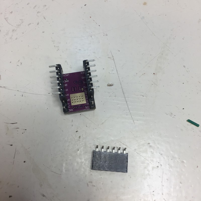
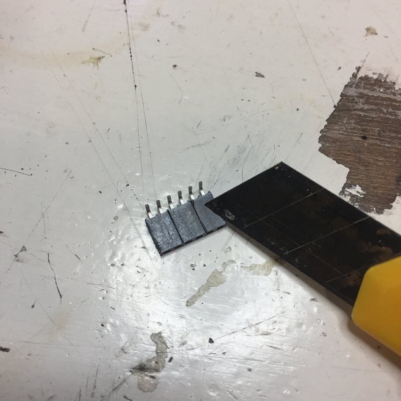
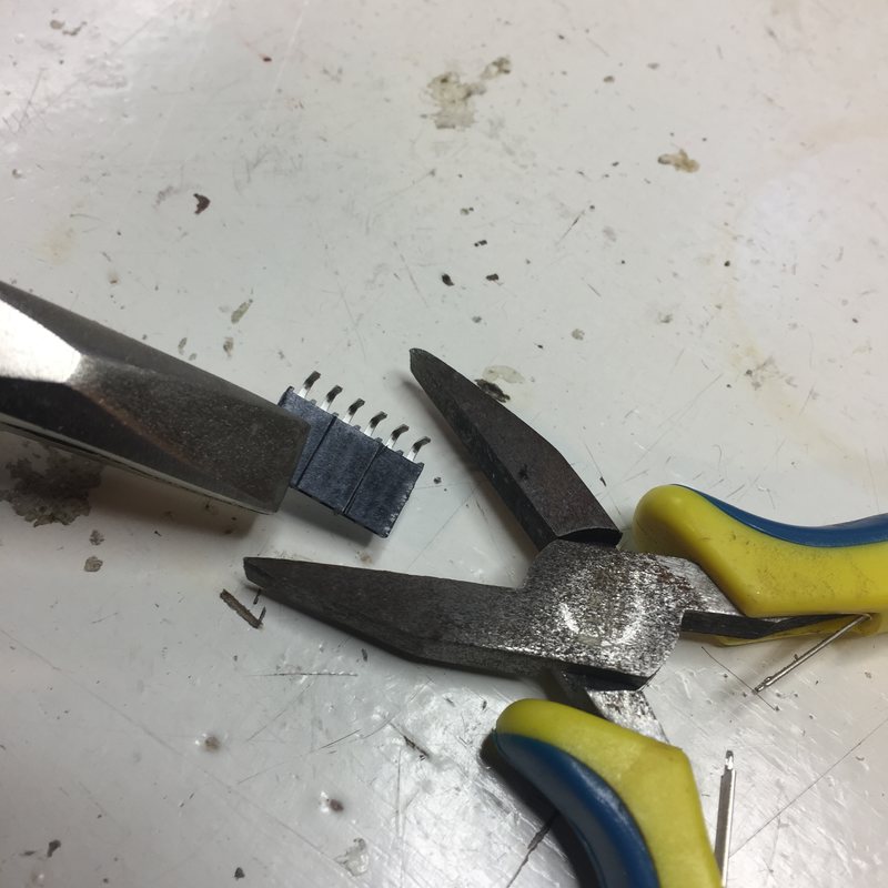
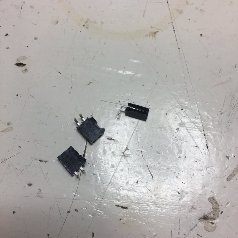
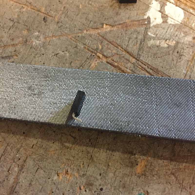
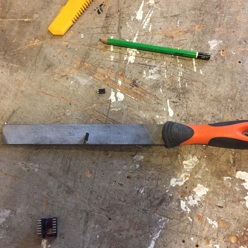
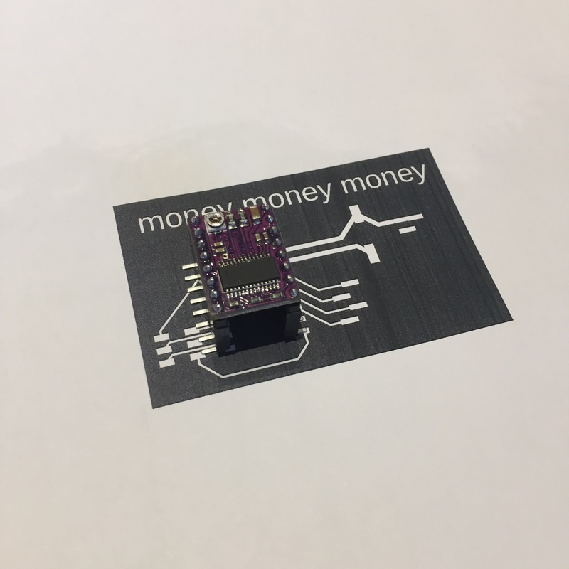
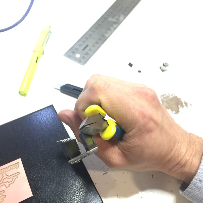
I found female headers in which to place the motor driver carrier. There were not enough pins for the driver, so following Emma's advice I split one by scoring it with a knife, splitting it with pliers, and filed down the edges to get them to sit snuggly beside each other.
Trying to find a footprint for the capacitor. The datasheet says that it is size G. So I google for SMD capacitor size G eagle footprint. HERE.
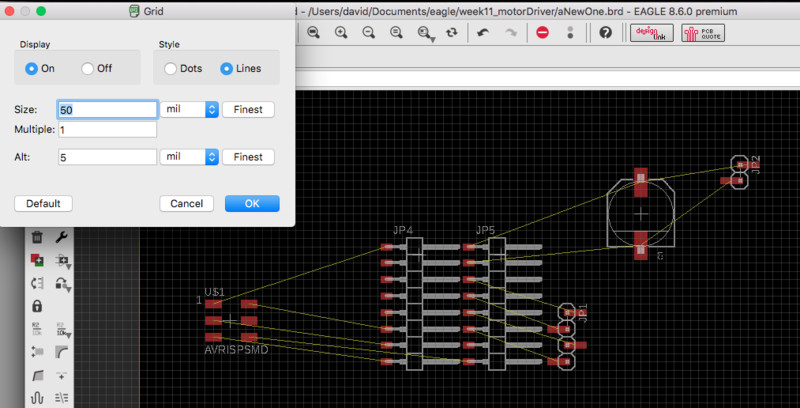
To place the two rows of headers at the right distance, I see that Eagle's default grid layout if 50 mil, and I know that the spacing between is 500 mil, so I place the two components 10 squares apart.


I printed out the traces PNG to check the placement and spacing of the components. It looked fine, but little did I know… only after I milled the board did I realise that it would create a huge piece of copper underneath the motor driver headers, and because the pads for those headers were so small, all of the headers would have shorted on that copper pad.
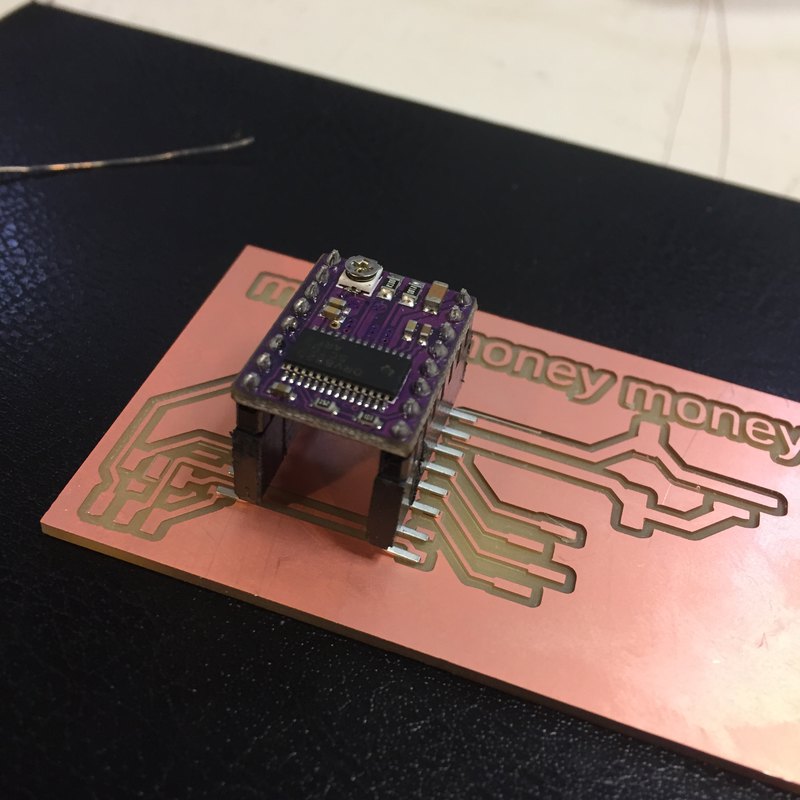
I almost freaked out. Emma said I should just isolate the pad with some electrical tape. Omg. It worked like a charm. I use pliers to bend the feet a little downwards in case the tape would have pushed them too far off the board.


A video on how to set the current on the stepper driver. The Pololu page states that the motor driver can supply 2.2A per coil, and the motor's datasheet wants 1.68A per coil. Pololu gives this equation for calculating the current: Current Limit = VREF × 2, by measuring the voltage at the VREF via on the board (or the video shows a trick of clipping the lead of the multimeter to the screwdriver turning the current-limiting trimpot). The desired current is 1.68 A, so VREF should read 1.68/2 = 0.84V
Check the wiring of the board with respect to the motor pins. If the polarity isn't correct, add a new connector to the wires? Consult with Emma first.
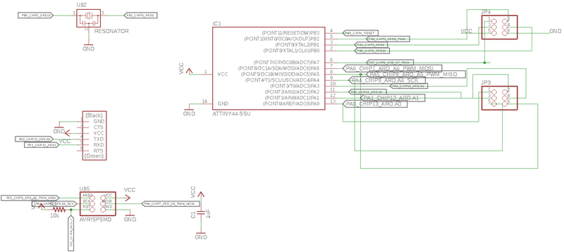
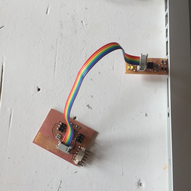
I had a look at the ATtiny Arduino pinout from highlowtech, because I got the idea from Johanna to just use the programmer header as an interface with the other board (because I was too lazy to figure out a cable solution for my straight headers) and found that I had access to Arduino pins 4,5,6, and the rest was GND and VCC and RESET.And, uh oh, I used the reset pin rather than the other available pin, the MOSI pin. Was this going to be a problem? I checked the highlowtech schematic and yes, it was going to be problem. Solution: cut the trace, solder cable to the MOSI pin. Or… I make a cable from the 6-pin programmer header to a flat connector on the attiny board. At least that way I can keep the programmer plugged in when I'm debugging. When considering connectos available here, I think maybe I should have used DIL headers rather than SIL, since that's what all of our connectors are for ribbon cable. Ugh. You know what, I'm going to redesign the ATTINY board. Fudge it.
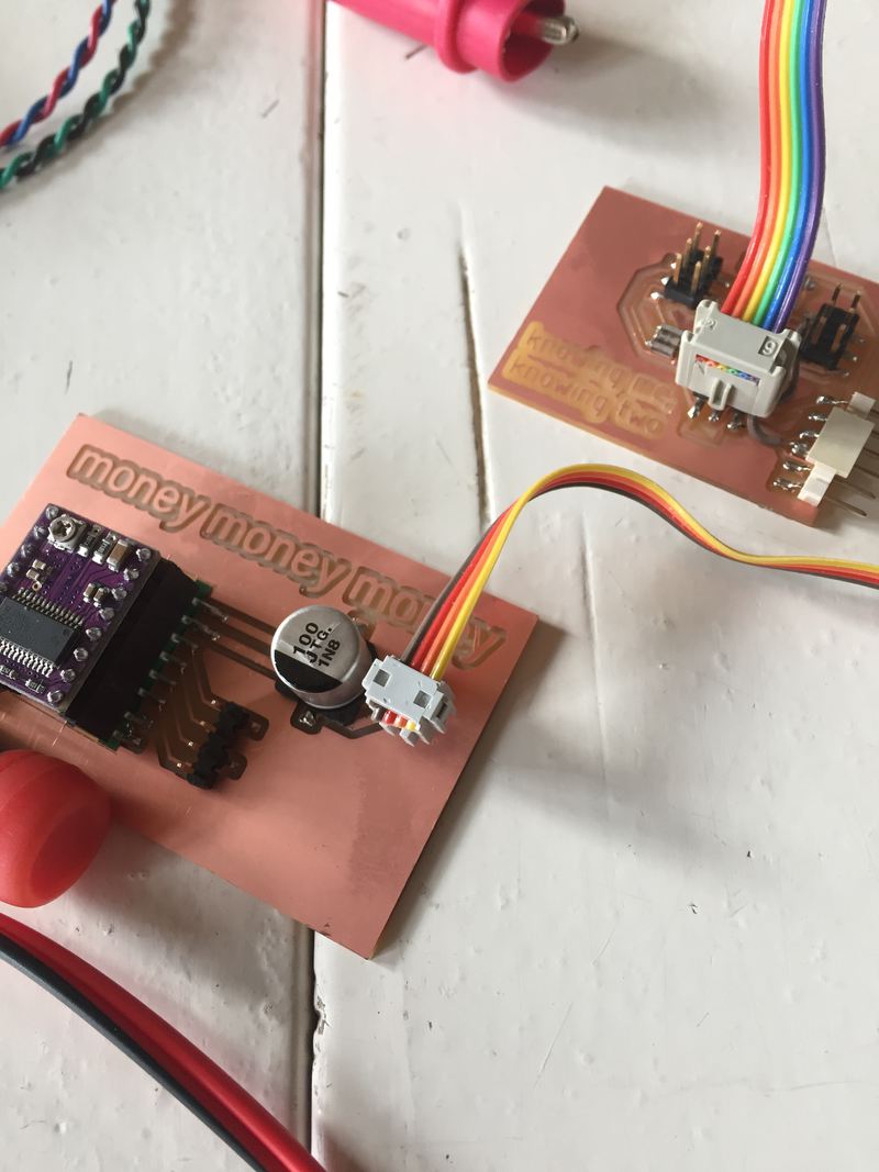
So Knowing Me, Knowing You became Knowing Me, Knowing Two. Here is the schematic (and I relabelled all the nets to include the Arduino pin and function), followed by Knowing Me, Knowing Two being programmed, and Knowing Me, Knowing Two connected to Money, Money, Money:
I got confused about wire colouring orientation and, in the pololu wiring, listing the motor pins as A1, A2, B1, B2, which don't correspond to the motor documentation. But when I compare the visual information on the pololu pinout with the visual orientation on the motor datasheet, it looks like it should work as black, green, red, blue, which is how the motor is wired to the connector. And then I find this instructable about steppers and this driver, and they list the colours as "rouge, blau, vert, noir", which has one of the pairs inverted (and the whole thing is backwards from what I just wrote, which is fine).
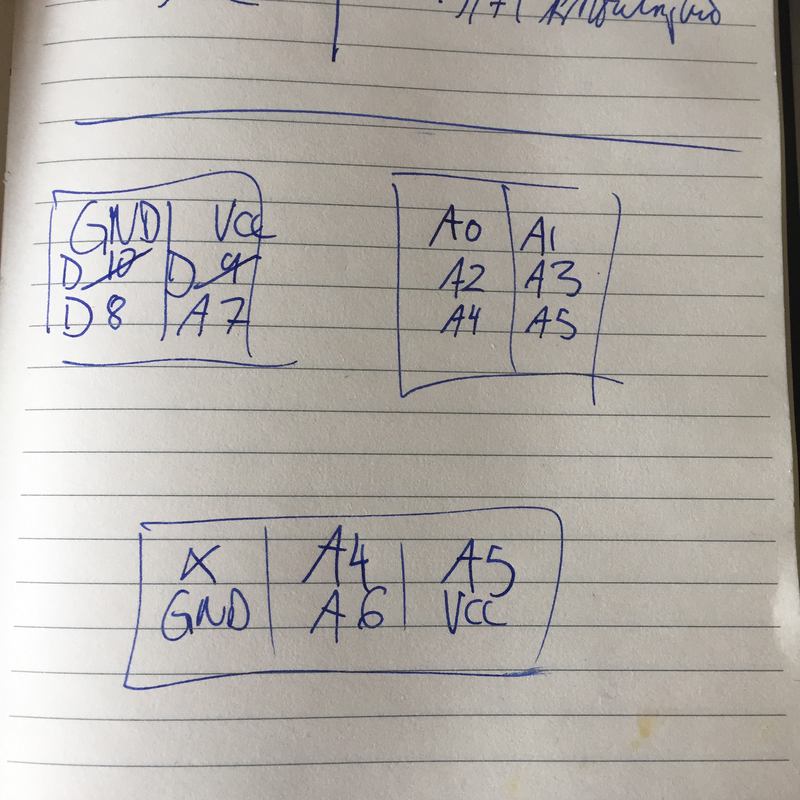
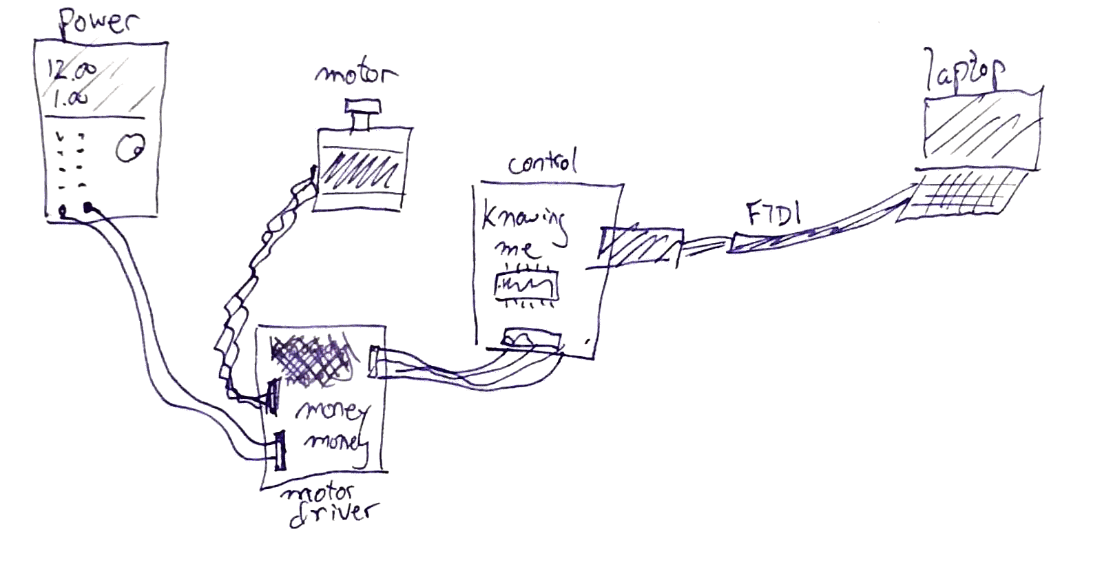
I found it very helpful to sketch pinouts of all my boards:
The next big problem was strange behaviour when trying to set the VREF on the motor controller. The youtube instructions didn't have 5V VCC connected, but Emma insisted that it was supposed to be connected. The next problem was that I thought I could use pins from the ATTiny to provide VCC to the motor board. Apparently not. The ATTiny can't provide the amount of current that might be required through its pins. I solved the problem by using jumper wires to connect everything. I think I will redesign the ATTiny board to have, by default, a VCC and a GND pin on each connector, making it easier to power connected boards, or else I set up pairs of pins that can get VCC and GND daisy-chained between boards. Here is me testing the VREF, what was in the cup?:

Here are pictures of everything connected (with the computer off-camera connected through the FTDI cable), and a schematic of how it's all wired:

For a while there Emma thought my circuit might have broken the motor driver, including her motor driver! Apparently not the case. Eventually I was able to get some kind of behaviour from the motor. Emma suggested using some code that she had found, without using the library. Once I understood it, it seemed much simpler than using the library. I modified the code to get some basic movement. It is very jerky, so I need to play around with the timings, the speed of retriggering, and the time of the pulse to the STEP pin. Here is the code:
/* Fab Academy stepper motor stuff
 *  David McCallum, 2018
 *  sintheta.org
 *  Code adapted from http://aconcaguasci.blogspot.nl/2016/11/arduino-cnc-shield-control-stepper.html
 */

#define EN        0

//Direction pin
#define X_DIR     4

//Step pin
#define X_STP     2


//DRV8825
int delayTime=30; //Delay between each pause (uS)
int stps=1;// Steps to move


void step(boolean dir, byte dirPin, byte stepperPin, int steps)

{

  digitalWrite(dirPin, dir);

  delay(100);

  for (int i = 0; i < steps; i++) {

    digitalWrite(stepperPin, HIGH);

    delayMicroseconds(delayTime);

    digitalWrite(stepperPin, LOW);

    delayMicroseconds(delayTime);

  }

}

void setup(){

  pinMode(X_DIR, OUTPUT); pinMode(X_STP, OUTPUT);


  pinMode(EN, OUTPUT);

  digitalWrite(EN, LOW);


  //pinMode(1, OUTPUT);
  //digitalWrite(1,HIGH);
  //pinMode(5, OUTPUT);
  //digitalWrite(5,LOW);

}

void loop(){

  step(false, X_DIR, X_STP, stps); //X, Clockwise

  //delay(100);

  //step(true, X_DIR, X_STP, stps); //X, Counterclockwise

  //delay(100);

}
The important code here is the step() function, which sets the direction pin, and then pulses the motor the requested number of steps by pulsing the STEP pin on the controller. I changed the durations in the formula until I got the motor twitching, as you'll see.
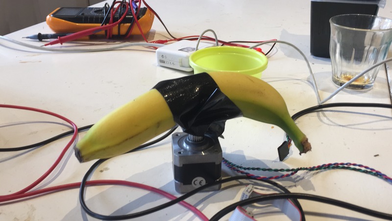
So here it is, your moment of effing zen, a spinning banana:
Banansterdam from David McCallum on Vimeo.
Hanna, the space architect, wants you to know that it's Hanna's banana.
A review of some mistakes I made
When trying to use this board for the machine design week I examined the schematic and board, and for some reason the FTDI RX pin is not connected in the schematic, even though it is connected in the schematic. So, wtf, Eagle? There are also some other connection weirdnesses. This is not so important, except that I wanted to do some debugging through the serial and now I can't read the serial. Also, the motor driver is using the 0 pin on the Arduino for some control, and that's also needed for the FTDI serial communication. So… that was an oversight, n'est-çe pas? Consider using the existing ISP header for the motor… or, you know, anything else.