Week 4: Eletronics production
Little things
I've updated my image-processing by creating a shell script to shrink the images and generate thumbnails. I can pass it an argument for which files to process, and the absence of an argument causes it to process all image files in the directory. It goes like this:
mkdir smaller
mkdir smaller/thumbnails [ $# -gt 0 ]; then
	FILENAMES=$1
else
	FILENAMES='*'
fi

mogrify -path smaller/ -resize 500x $FILENAMES
mogrify -path smaller/thumbnails -define jpeg:size=400x400 -thumbnail 200x200^ -gravity center -extent 200x200 smaller/$FILENAMES
Previous knowledge
I have considerable experience soldering, both through-hole and SMD, so I didn't expect that part of the week to be a challenge, but from my experience learning to solder, this will be the hardest thing for those who haven't soldered before. I have made PCBs using transfers and etchant, but have never milled them. I'm excited about this. I have some experience using ISPs and Arduinos as ISPs, but I hope this week will make me more comfortable with the procedure.
Group assignment
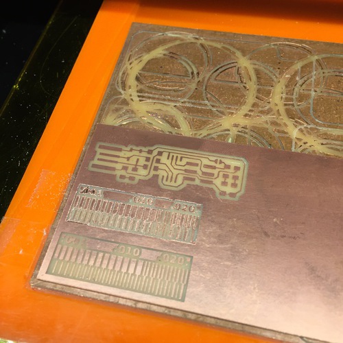
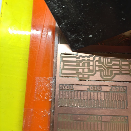
We characterised the milling machine using the test template provided by Neil Gershenfeld, found here. See our results here.
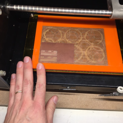
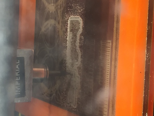
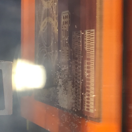
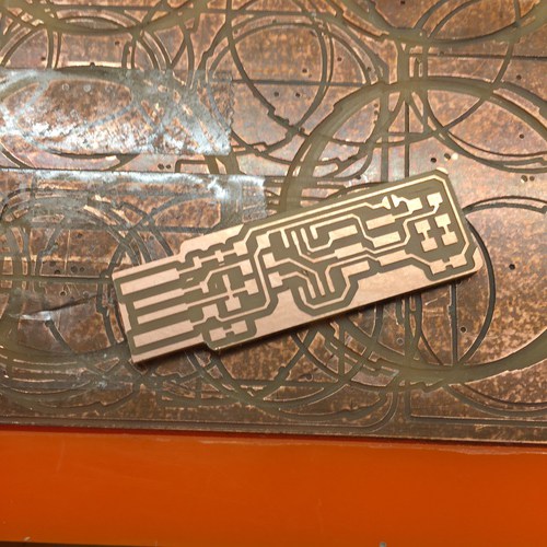
Milling the board
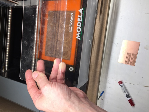
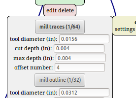
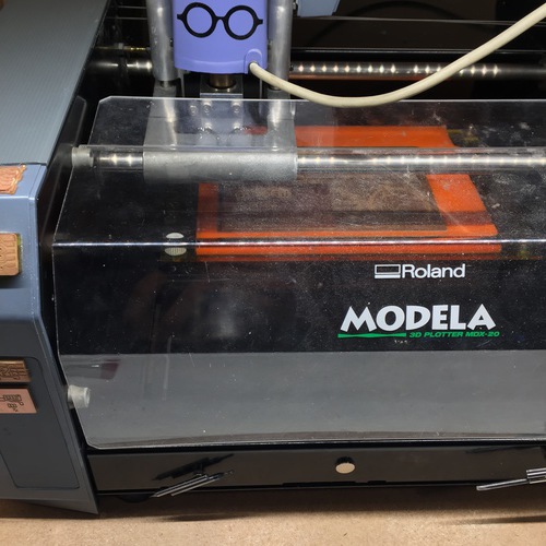
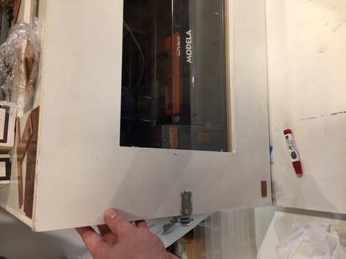
There are two PNG files for milling the board. One is the traces, and the other is the outline of the board. The traces will be milled with a 1/64" bit and the outline with a 1/32" bit. We will be milling FR1 boards (a paper substrate) with a Roland MDX-20 milling machine. The FabISP design we are using is Brian's.
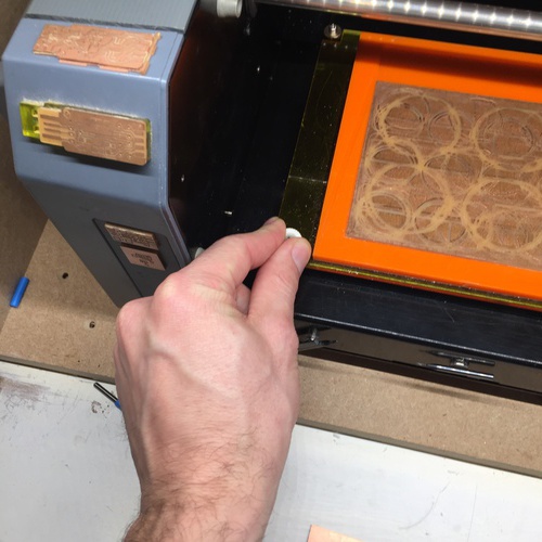
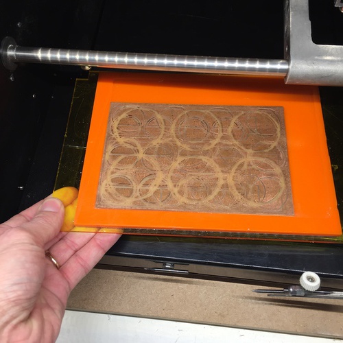
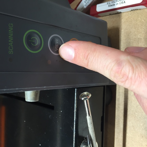
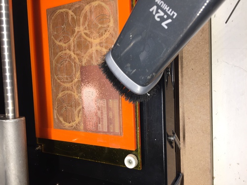
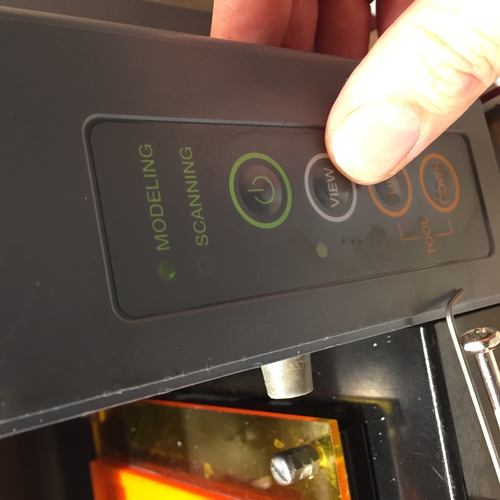
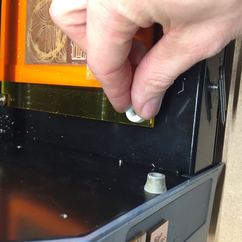
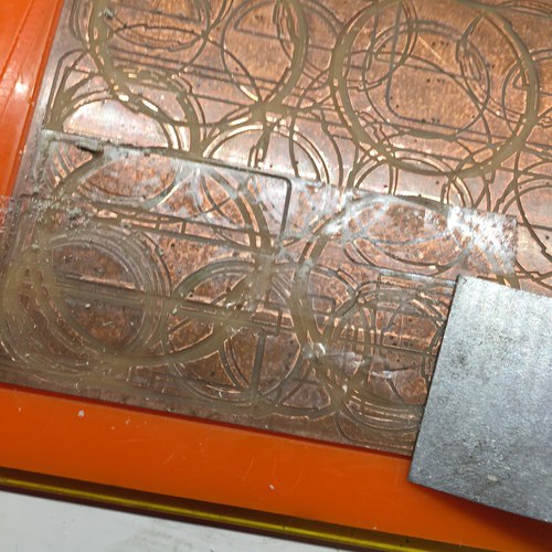
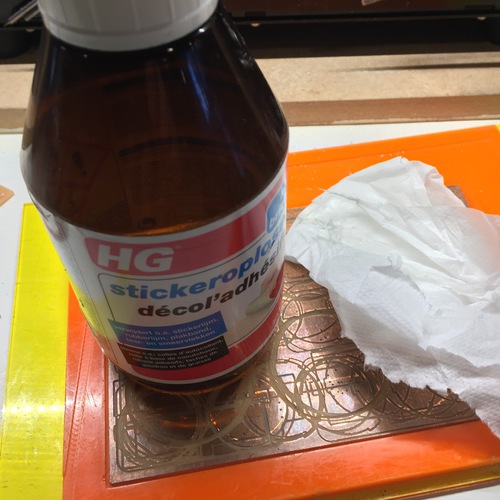
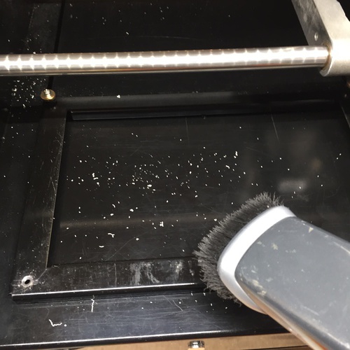
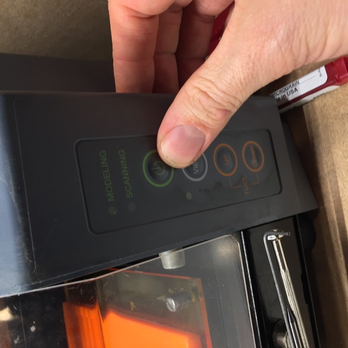
Turn on the machine with the on button. If there is a usable plate already on the bed, use the existing plate. If it's not usable, prepare the bed. Prepare the bed of the machine by removing the front to screws, place them on the magnet for safe keeping. Scrape the board off. Scrape the tape off, peel it. Clean the bed with a glue remover and paper towel. Then check for dust and paper, and brush and vacuum as needed to clean it.
Place strips of tape on the board beside each other but not overlapping. Stick the board to the tape and press firmly. Replace the bed and the screws.

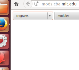
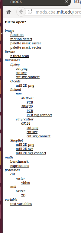
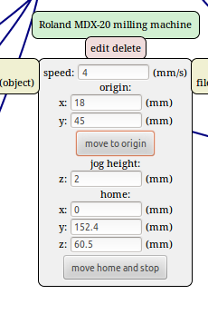
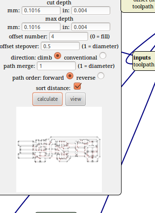
Turn on the computer, boot to Linux, and run the mods programme by clicking the link "link to mods" on the desktop, or at http://mods.cba.mit.edu . In mods, click Programs - Open Server Program. Then select Roland - Mill - MDX20 - PCB in the menu. Mods loads the programme for the machine. Click "select PNG file", load the traces PNG, and mods does some magic. Select "mill traces". Select "calculate". The milling path is then calculated. A new tab opens showing the milling path. You can control Offset, which determines how many paths are milled. Stepover controls the overlap between milled paths. .5 is good. Don't change speed and job height.


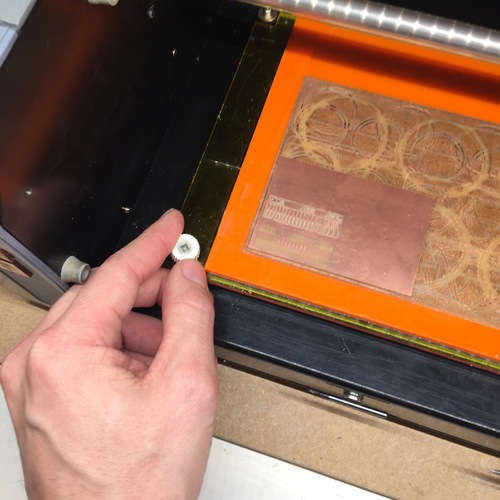
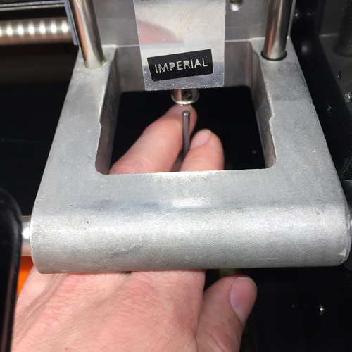
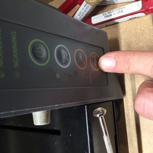
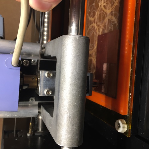
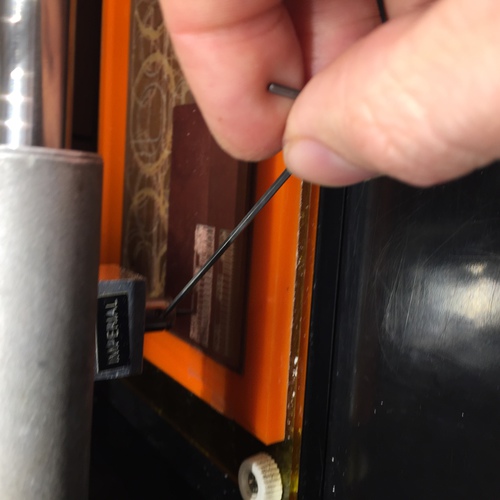
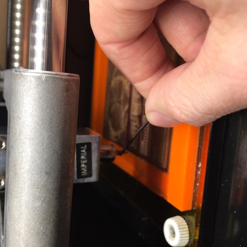
Now set the tool in the machine. Use the hex key on the magnet to loosen the collet. Hold the bit while doing this so it doesn't drop. Replace the bit if you need to. Retighten the collet very gently. Then do the Z calibration, to set the correct height of the bit. Set the bed height with the Up and Down buttons on the machine, then loosen the collet and place the bit so that it is gently touching the copper. Twist the bit to remove dust. Retighten the collet gently.

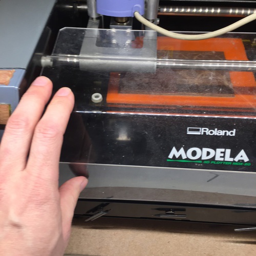
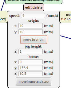
Connect the machine. On the desktop, click the link "serial server, then in Mods click "serial server - open" and the machine and the computer will be communicating. Set the x-y origin in mods, and press "origin". Adjust as needed. Make a note of the values. Always recalculate after changing the origin! Click "send file", and it cuts! Put on the machine cover and the enclosure door. Otherwise it's noisey!


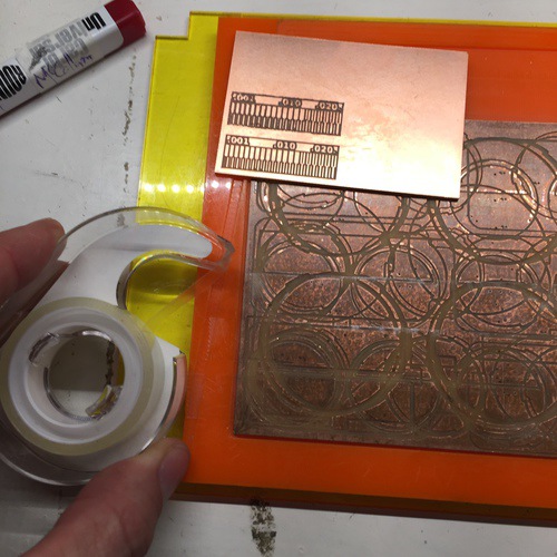
When it's finished, vacuum away the dust. If everything is fine, replace the bit with a 1/32" bit. Calibrate the Z again. Set the origin to 0,0. Move the bit up. Then move it to the origin that you recorded. Select the outline PNG, click "Mill outline", recalculate. The depth should be less than the diameter of the bit. 2/3 is OK, 1/2 is very safe. Click "send file" and cut the outline. When finished, check to see that it cut, and clean the machine with the brush and vacuum. If the board is finished, clean the bed with goo remover.
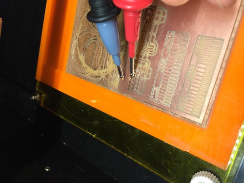
I had a problem to solve! Part of my traces were not cut low enough. I used a multimeter to check continuity between areas of copper that should have been separated and, sure enough, they made a connection. I followed Zaerc's advice to simply set the cut depth to 0.1mm lower and remill the board. It worked great!


Soldering the parts
The components:
- 1x ATtiny45 or ATtiny85
- 2x 1kΩ resistors
- 2x 499Ω resistors
- 2x 49Ω resistors
- 2x 3.3v zener diodes
- 1x red LED
- 1x green LED
- 1x 100nF capacitor
- 1x 2x3 pin header
I have no pictures of this. It's hard to hold a phone while soldering. I've done this before and had no problem. I followed the BOM and layout provided on Brian's page. Clean the iron tip, place it touching both the pad and the component, gently flow some solder to the heated parts, remove the solder, hold the iron until you're satisfied, remove the iron.
I did learn something about SMD soldering. I had been taught, when learning on through-hole components, to "tin" the iron before soldering to increase the surface area to increase heat transfer to the components. After watching Emma's demonstration, where she didn't tin the iron for SMD components, I tried doing it like that, and my SMD joints were much prettier, much less bulbous. So, for SMD, don't tin the iron!
I taped a piece of cardboard to the bottom of the board to give it more thickness in the USB port.
Programming the board
I followed the rountine on Brian's page. I installed Crosspack. I downloaded
the firmware. I built the hex file with the command make.
I didn't need to edit the makefile, because I was already using a usbtiny
as the programmer.
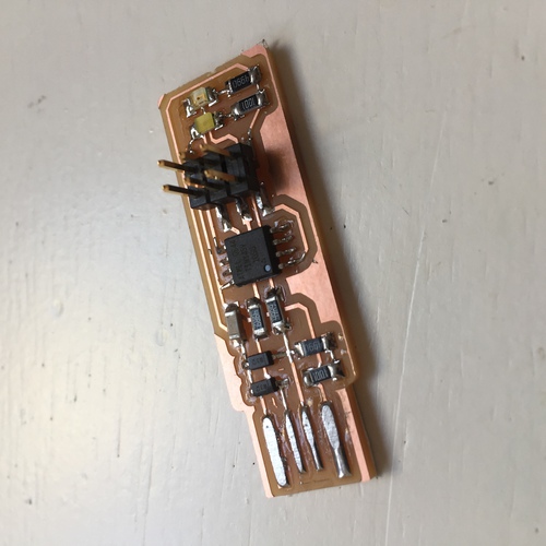
I connected my programmer
with another using a ribbon cable. It looked like this:

I had an error making the firmware, it looked like this:
egon:fts_firmware_bdm_v1 david$ make
avr-gcc -mmcu=attiny45 -Wall -DF_CPU=16500000UL -I. -funsigned-char -funsigned-bitfields -fpack-struct -fshort-enums -Os -Iusbdrv -c main.c -o main.o
make: avr-gcc: No such file or directory
make: *** [main.o] Error 1
I tried restarting terminal after install crosspack. Success! Compiled with no errors. Then I did the commands
$ make flash and $ make fuses and they all worked just fine.
Then Emma's excitement caused a problem. I was continuing to follow Brian's instructions
when Emma told me to test my board as a programmer, plug in a second board that she handed
me, and try the command $ avrdude -c usbtiny -p t45. And I got the
error:
avrdude: initialization failed, rc=-1
         Double check connections and try again, or use -F to override
         this check.


avrdude done.  Thank you.
I was told by emma and Zaerc to check the pins for continuity errors. Pins checked fine.
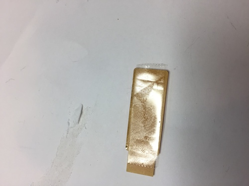
I filed the USB contacts more to make them more level. Then Emma realised that she was
so excited, that she interrupted me before I could blow the reset fuse. I ran the code
$ make rstdisbl.
Then I did the test of connecting
a board Emma had, with mine as the programmer, and ran the test again: $ avrdude -c usbtiny -p t45.
And got the response:
avrdude: AVR device initialized and ready to accept instructions

Reading | ################################################## | 100% 0.01s

avrdude: Device signature = 0x1e930b (probably t85)
avrdude: Expected signature for ATtiny45 is 1E 92 06
         Double check chip, or use -F to override this check.

avrdude done.  Thank you.
Emma says this is fine. It sees the second board but it's not the kind of board that it was expecting. This says that everything works. Yay!