☢ Group 1 ☢ Group 2 ☢ Group 3 ☢
Designing the file
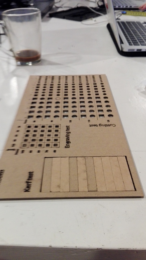
This week's group assignment is to test the fab academy's laser cutter in a variety of settings and dimensions.Looking at past tests and settings, the test we use combines the following:
Engraving table, comprised of Power columns and Speed rows.
Cutting table, comprised of Power columns and Speed rows.
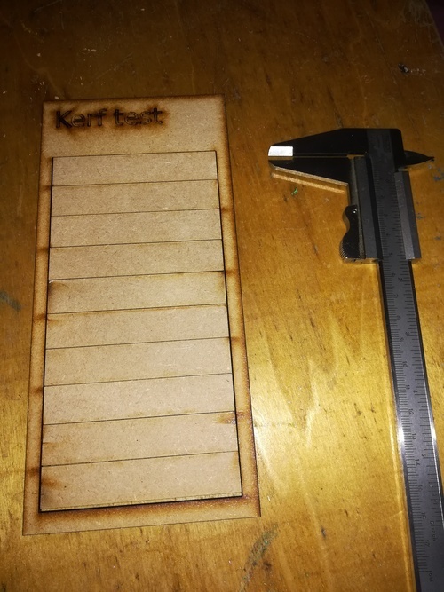
Kerf measuring, comprised of 10 rectangles and 11 lines (cuts), whereast the total vertical material loss is divided by the 11 cuts made, and the result being the machine's Kerf.
The material we are testing the machine on is MDF.
It is also important to note that in this assignment our group is testing two different laser cutting machines.
The software used to make the test schematics is Adobe Illustrator.
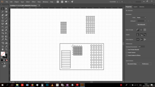
The first object made is of course a big rectangle, which will contain all the various tests.
The containing rectangle's dimensions are 150pt x 200pt.
It's dimensionst are ultimately meant to be 15cm x 20cm (150mm x 200mm).
The following step was to add a grid to the interface, to make work easier. In the overhead menu bar, it's in View > Show Grid, and then View > Snap to Grid.
The grid's settings were changed to a grid every 10 points in Edit > Preferences > Guides & Grid, and in the same settings also change the grid to have 10 subdivisions. It's gonna be easy to measure things like this.
The rectangle's filling was made invisible in the left hand color menu:
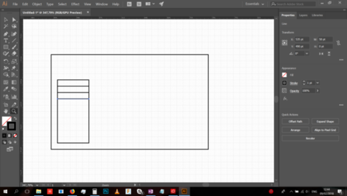
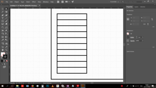
The first added is the Kerf test. It is 100pt tall (10cm tall in total), with 10 rectangles in it, and 11 cut lines. It is 50pt wide. The loss will only be measured vertically.
Then a line was added at every grid line in the Kerf test to divide it into 10 equal sized smaller rectangles:
Next is the engraving test.
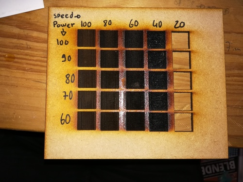
The engraving test will test 5 power and 5 speed configurations to a total of 25 engravings.
Power will be 100, 80, 60, 40, 20.
Speed will be, for safety concerns, starting at 100 and dropping by 10 each time, so as not to get too slow. Thus it will be 100, 90, 80, 70, 60, 50.
Because engraving is slow, these engraving test will be dimensionally small so as to save on time, energy and machine wear.
The engraving is tested in squares, each 10pt x 10pt in size.
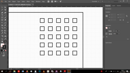
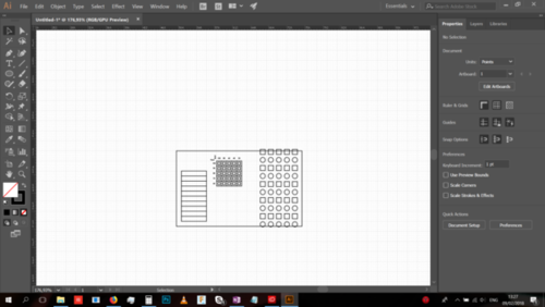
These little engraving squares were then placed into a graphic table, with the surrounding outlines being meant for a low power cutting that will simply mark them black, because even in a functional design - abandoning aesthetics is both sinful and unjust.
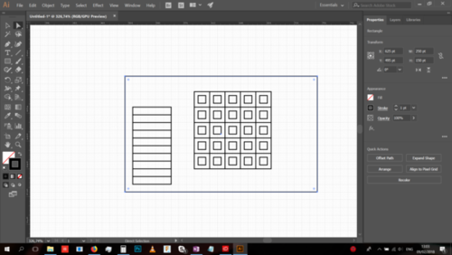
It is now turning out that the dimensions of the engraving test are too large, so they are scaled down to 50%. Meaning each engraving square is now 5pt x 5pt, or 5mm x 5mm.
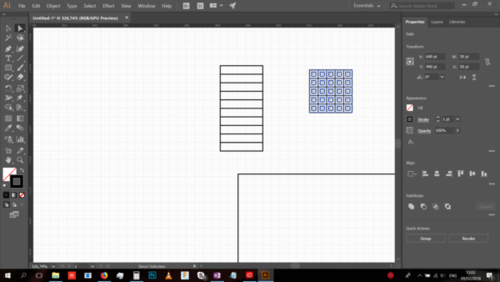
Adding the engraving test title and settings table (using the text tool):
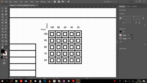
The test font (Gill Sans MT) was chosen due to it's simple shapes, and for the purpose of further simplifying the machine's operations and reducing use of time and energy.
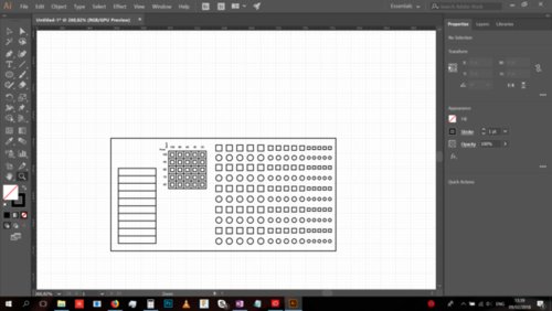
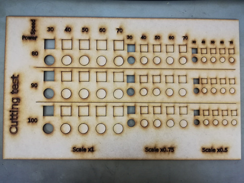
The final test is Cutting.
This will measure again a 5 by 5 table of configurations, but will repeat said settings on multiple size shapes to a total of 3 times. Every table item will contain one square and one circle. In total 5x5x3x2 (150) cuts of various speed/power configurations and sizes and shapes.
A single row was made:
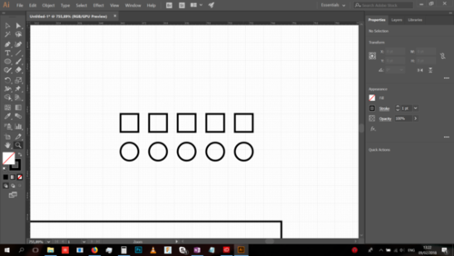
Each element was 10pt x 10pt (the circles had a diameter of 10pt).
Multiple copies were made one under the other to create a single table.
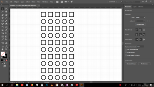
It had not fit into the containing rectangle very well, and ended up too big.
So it was scaled down by 20 percent.
Because each item is 10pt x 10pt, it makes for a convenient direct 8pt x 8pt scale.
The gaps between them were also reduced.
The fit was now spectacular:
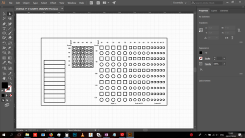
The table was then copied, and scaled down to 75%.
Then another copy was made and scaled down to 50%.
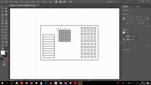
Unfortunately the limitations of the bounding box are making themselves clear now so the box was re-designed to accommodate all the tests beautifully and functionally, by increasing it's width from 200pt to 300 pt, and it's height from 150pt to 160pt.
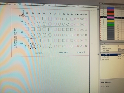
The table's power, speed and scale settings are then added.
Based on some tests performed in class, a good starting power/speed combination for MDF is 40 Speed and 100 Power, so this will be used as a good anchoring point to decide on theo ther values to be tested.
Thus - the power values which will be tested are: 80, 90, 100, 110, 120
The speed values will be: 30, 40, 50, 60, 70
The scale modifiers are 1, 0.75 and 0.5.
A few final additions and modifications / line colorations:
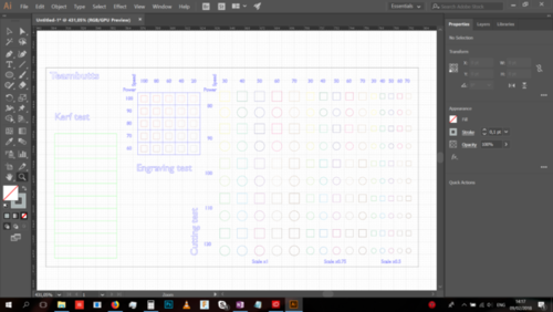
The following is the color coding for the machine:
Blue: Cut, low power 30 and high speed 60, to ensure the lines don't cut through the material. It is also a kind of test in and of itself, testing "engraving" lines with the cut tool.
Green: Cut using 100 Power and 40 Speed, which appears to be a reliable MDF cutting setting.
All the other colors (there's too many to specify here) are meant to correspond to their appropriate Engraving / Cutting settings as specified in the Columns / Rows.
Testing the lasercutter: Xavier's story
I put inside the lasercutter a 3mm mdf plank, set the focus and launch the software, SmartCarve.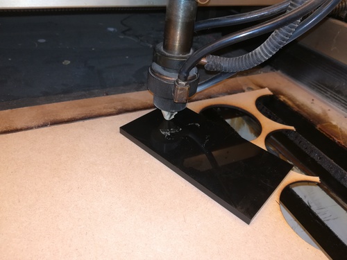
I import the DXF file and set its position in the plank. I have to "scatter group" in order to select each stroke separately. I also set speed and power for each test. 15 different settings.
On the machine, I set the origin (where the zero is for this cut), press "Carve Out" and the machine is rolling. The result:
With this machine, you have to set the speed under 30 mm/s to have a good cut.
Now, kerf.
For this one I set: speed: 25 mm/s power: 90%. I've tried with 30 mm/s power 100% but I didn't have good result.
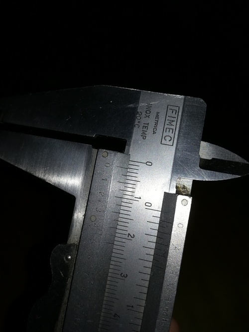
I mesure 2 mm, divided by 11, I've 0.18 mm kerf.
Now, engraving test:
SmartCarve makes engraving only with bitmap images. So I have to draw a square in Paint (lol), save it in .bmp, import it in SmartCarve and copy-paste it for each settings.
At the end, I have this. So I think good settings are 100 mm/s and 100%.
Testing the lasercutter: Dima & Johanna's story
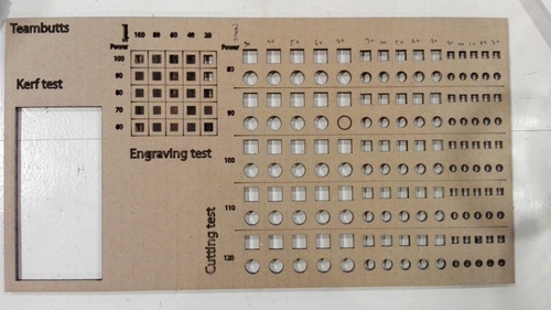
In the lab, when pushing the test schematic into the machine, we found that the font is not existing on the machine, doesn't get imported, and have had to change the font, which is unfortunate as it was specifically selected :(.
This was because I didn't use the Object > Expand command at home on the text, and so it was relying on local machine fonts, rather than simply being a shape.
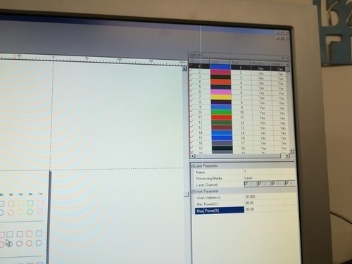
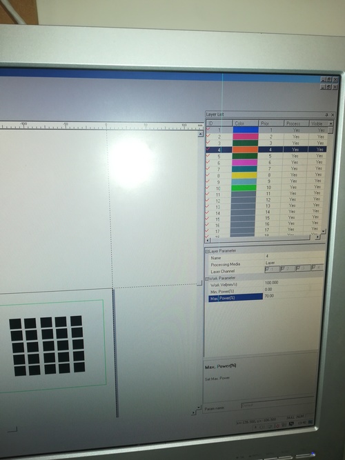
The bulk of the time was spent on making the machine software properly read the schematic. First problem was that the machine's software actually has a very limited color pallette, and so the color coding which I have done could not be properly imported, leaving me to re-code all the objects. Because the count of objects exceeded the number of unique colors the software supported, the test had to have been done in two batches, engraving, and cutting.
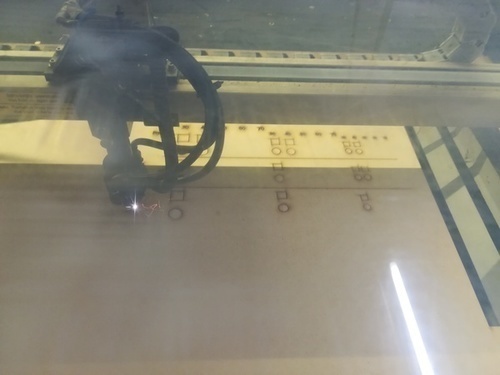
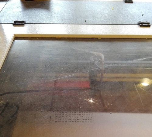
We set the starting point of the machine near the top left, which turned out to be very dark and made it hard to see what was going on:
The setting initially planned for also got changed, for the engraving. That is, the original planned power values - 100, 80, 60, 40, 20 - instead of being absolute values, simply became % values of the default power the machine provides. This is because it provided a low power value off the get go, 30, so in order to avoid a fire, this change was made. This means the power values were simply 1*30, 0.8*30, 0.6*30, 0.4*30 and 0.2*30.
After pulling out the test from the machine, every single cutting item on the cut test table was cut out perfectly. This means that none of the different settings we tried had any difference in how they acted with the material.
This turned out, a bit later, to be because we used cardboard instead of the MDF we were intending, so this was the result of a brainfart.
And speaking of brainfards - as soon as I pulled the thing out of the machine, the general tiredness and frustration at getting the thing read my file in the first half of the test resulted in me basically throwing away all the bits out of the Kerf test, as seen in the image above being empty. I realized my error and rescued 9 of the 10 pieces out of the trash.
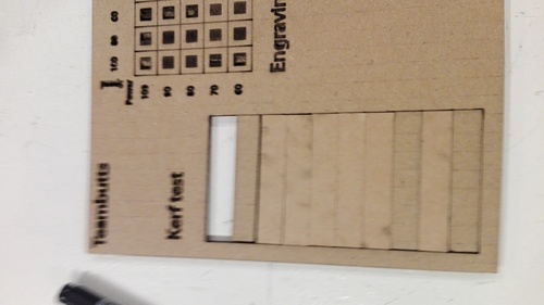
Then sat to measure the existing pieces, do some math, and try to calculate the Kerf without the last 10th piece.
Thankfully at that point Emma came around, checked things out, told me I'm adding errors on top of errors by doing this, and helped me rescue the last 10th piece of the test from the trash can.
After that the kerf was measured accurately - the total material loss was 2.52mm, divided by 11 it makes 0.22909091, which is the final figure of the kerf.
Conclusions:Xavier, Imal lasercutter:
Kerf: 0,18mm
Cut: 100% power, 30 mm/s speed
Engraving: 100% power, 100 mm/s speed
Dima & Johanna, Waag lasercutter:
Kerf: 0.22909091mm