Week 12
Getting started with Output Devices
This weeks assignments was to get familier with output devices....... and add some output to my board.....
Last week I was not able to complete the assignment as I was working on a general IO board ... which is still under debugging state ...... So this week I tried to make a board which would be having both the inputs and the outputs ....
After going through Lab inventory ...... I decided to take Input using LDR and use a buzzer as and output ..... I wanted to program a board which changes the buzzer output according to the light which is falling over the LDR ...
Step 1
Learn about LDR
The first step was to understand how LDR works ...... What I understood was ..... its resistance changes according to the light which falls over it ..... but a Microcontroller can not understand resistance changes directly ..... it can only understand Voltage changes ...... So I decided to make a voltage divider with a random resistance .... which in my case was 10K resistance.....
Step 2
The second step was to understand how the buzzer would be generating sound ..... its because it you provide constant dc (analog voltage) of different magnitude it wont sound ..... it needs a PWM Signal to produce sound .....

For better understanding of PWM Signals refer this LINK
Also referance from this link can be used : Arduino and Buzzer Interfacing
Now that basics were clear ..... I moved ahead with designing PCB for the same .....
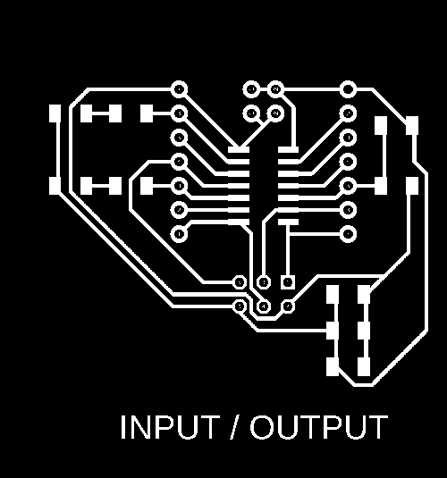
I decided to make a general PCB whose all the pins can be accessed using jumper wires

I also made designated some pins for Power .....


Last week I designed the PCB with 10mils tracks .... It worked like a charm but this time when I tried to mill out 10mils tracks, the tracks were not good .... this is what I got after milling .......


So I redesigned the PCB with new design rules, with minimum track width of 16mils and clearance of 10mils minimum..... This time the PCB was perfect ..... and now it was ready to mount components ....
In this PCB the tracks around AVR ISP Header were very fine .... and due to overheating the tracks were gone ...... So I connected the VCC line manually and used other pins to program the board ...... (tested, and working)
Now it was time to program the board ..... I decided to program the board using Arduino IDE......Before programming .... Lets understand arduino Pin Designation and ATTINY44 Pins....

 So According to this Pin Connections were as :
 1. LDR Input is on pin 10 of ATTINY44, that means Analog pin 3 on Arduino
 2. LED & Buzzer Output was on pin 5 of ATTINY44, that means Analog pin 8 on Arduino, note: this pin is a PWM pin.
 3. Buzzer was connected between pin 5 and 6 of ATTINY44, i.e pin 8 and 7 on Arduino.
 4. MISO pin of ISP Programmer connected to >> PIN 8
 5. MOSI pin of ISP Programmer connected to >> PIN 7
 6. SCK  pin of ISP Programmer connected to >> PIN 9
 7. RST pin of ISP Programmer connected to >> PIN 4
 8. VCC to VCC
 9. GND to GND
Now it was time to program the board .....
In the Setup Function : I have declared pin 7 as OUTPUT and made it LOW, I have done this to provide ground to the Buzzer.

In the Main Loop Function : The first Line is about reading Sensor Value. analogRead() would be reading the voltage value at A3 Pin,
                            the values controller would be recieving after ADC would be in a range of 0-1023.

                          : The second line is about converting the recieved value in the range of 0-1023 to 0-255 as  for writing
                            analog value (PWM),we need to pass values between 0-255. So Map function in arduino is used for the same.
It is a very basic program ...... which simply takes analog values, map it and then write analog value to Pin 5.
Pin 7 is pulled LOW in the setup section as buzzer is placed between PIN 8 and PIN 7.
The first step is to burn bootloader over the board Go to Tools > Burn Bootloader

Then after this step Go to Sketch > Upload using bootloader

Note: Make sure that the Board, Processor, Clock and Programmer are selected correctly in the tools option as shown above.
Testing
Conclusion
From the video, It may be observed that the volume of buzzer changes according to the light intensity........ and both the input/output was realized onto a same board .....
Download All Files Download Board Files/CodeInterfacing OLED with the Final Board
Sneak Peak at the Final Board


Now here is the Board layout


For detailed explaination refer this link Final Project Documentation
Now Interfacing OLED With the Board
I used Adafruit Library to interface OLED with the Board

This was the schematic for interfacing OLED with arduino ..... the Pins I used on my Boards were 5,6,7 and 8.
Code
#include "SPI.h"
#include "Wire.h"
#include "Adafruit_GFX.h"
#include "Adafruit_SSD1306.h"

// If using software SPI (the default case):
#define OLED_MOSI   5
#define OLED_CLK   6
#define OLED_DC    7
#define OLED_CS    9
#define OLED_RESET 8
Adafruit_SSD1306 display(OLED_MOSI, OLED_CLK, OLED_DC, OLED_RESET, OLED_CS);

/* Uncomment this block to use hardware SPI
#define OLED_DC     6
#define OLED_CS     7
#define OLED_RESET  8
Adafruit_SSD1306 display(OLED_DC, OLED_RESET, OLED_CS);
*/

#define NUMFLAKES 10
#define XPOS 0
#define YPOS 1
#define DELTAY 2

#define LOGO16_GLCD_HEIGHT 16
#define LOGO16_GLCD_WIDTH  16
static const unsigned char PROGMEM logo16_glcd_bmp[] =
{ B00000000, B11000000,
B00000001, B11000000,
B00000001, B11000000,
B00000011, B11100000,
B11110011, B11100000,
B11111110, B11111000,
B01111110, B11111111,
B00110011, B10011111,
B00011111, B11111100,
B00001101, B01110000,
B00011011, B10100000,
B00111111, B11100000,
B00111111, B11110000,
B01111100, B11110000,
B01110000, B01110000,
B00000000, B00110000 };

#if (SSD1306_LCDHEIGHT != 32)
#error("Height incorrect, please fix Adafruit_SSD1306.h!");
#endif

void setup()   {
Serial.begin(9600);

// by default, we'll generate the high voltage from the 3.3v line internally! (neat!)
display.begin(SSD1306_SWITCHCAPVCC);
// init done

// Show image buffer on the display hardware.
// Since the buffer is intialized with an Adafruit splashscreen
// internally, this will display the splashscreen.
display.display();
delay(2000);

// Clear the buffer.
display.clearDisplay();

// draw a single pixel
display.drawPixel(10, 10, WHITE);
// Show the display buffer on the hardware.
// NOTE: You _must_ call display after making any drawing commands
// to make them visible on the display hardware!
display.display();
delay(2000);
display.clearDisplay();

// draw many lines
testdrawline();
display.display();
delay(2000);
display.clearDisplay();

// draw rectangles
testdrawrect();
display.display();
delay(2000);
display.clearDisplay();

// draw multiple rectangles
testfillrect();
display.display();
delay(2000);
display.clearDisplay();

// draw mulitple circles
testdrawcircle();
display.display();
delay(2000);
display.clearDisplay();

// draw a white circle, 10 pixel radius
display.fillCircle(display.width()/2, display.height()/2, 10, WHITE);
display.display();
delay(2000);
display.clearDisplay();

testdrawroundrect();
delay(2000);
display.clearDisplay();

testfillroundrect();
delay(2000);
display.clearDisplay();

testdrawtriangle();
delay(2000);
display.clearDisplay();

testfilltriangle();
delay(2000);
display.clearDisplay();

// draw the first ~12 characters in the font
testdrawchar();
display.display();
delay(2000);
display.clearDisplay();

// draw scrolling text
testscrolltext();
delay(2000);
display.clearDisplay();

// text display tests
display.setTextSize(1);
display.setTextColor(WHITE);
display.setCursor(0,0);
display.println("Hello, world!");
display.setTextColor(BLACK, WHITE); // 'inverted' text
display.println(3.141592);
display.setTextSize(2);
display.setTextColor(WHITE);
display.print("0x"); display.println(0xDEADBEEF, HEX);
display.display();
delay(2000);
display.clearDisplay();

// miniature bitmap display
display.drawBitmap(30, 16,  logo16_glcd_bmp, 16, 16, 1);
display.display();

// invert the display
display.invertDisplay(true);
delay(1000);
display.invertDisplay(false);
delay(1000);
display.clearDisplay();

// draw a bitmap icon and 'animate' movement
testdrawbitmap(logo16_glcd_bmp, LOGO16_GLCD_HEIGHT, LOGO16_GLCD_WIDTH);
}


void loop() {

}


void testdrawbitmap(const uint8_t *bitmap, uint8_t w, uint8_t h) {
uint8_t icons[NUMFLAKES][3];

// initialize
for (uint8_t f=0; f< NUMFLAKES; f++) {
  icons[f][XPOS] = random(display.width());
  icons[f][YPOS] = 0;
  icons[f][DELTAY] = random(5) + 1;

  Serial.print("x: ");
  Serial.print(icons[f][XPOS], DEC);
  Serial.print(" y: ");
  Serial.print(icons[f][YPOS], DEC);
  Serial.print(" dy: ");
  Serial.println(icons[f][DELTAY], DEC);
}

while (1) {
  // draw each icon
  for (uint8_t f=0; f< NUMFLAKES; f++) {
    display.drawBitmap(icons[f][XPOS], icons[f][YPOS], bitmap, w, h, WHITE);
  }
  display.display();
  delay(200);

  // then erase it + move it
  for (uint8_t f=0; f< NUMFLAKES; f++) {
    display.drawBitmap(icons[f][XPOS], icons[f][YPOS], bitmap, w, h, BLACK);
    // move it
    icons[f][YPOS] += icons[f][DELTAY];
    // if its gone, reinit
    if (icons[f][YPOS] > display.height()) {
      icons[f][XPOS] = random(display.width());
      icons[f][YPOS] = 0;
      icons[f][DELTAY] = random(5) + 1;
    }
  }
 }
}


void testdrawchar(void) {
display.setTextSize(1);
display.setTextColor(WHITE);
display.setCursor(0,0);

for (uint8_t i=0; i < 168; i++) {
  if (i == '\n') continue;
  display.write(i);
  if ((i > 0) && (i % 21 == 0))
    display.println();
}
display.display();
}

void testdrawcircle(void) {
for (int16_t i=0; i0; i-=5) {
  display.fillTriangle(display.width()/2, display.height()/2-i,
                   display.width()/2-i, display.height()/2+i,
                   display.width()/2+i, display.height()/2+i, WHITE);
  if (color == WHITE) color = BLACK;
  else color = WHITE;
  display.display();
}
}

void testdrawroundrect(void) {
for (int16_t i=0; i=0; i-=4) {
  display.drawLine(0, display.height()-1, display.width()-1, i, WHITE);
  display.display();
}
delay(250);

display.clearDisplay();
for (int16_t i=display.width()-1; i>=0; i-=4) {
  display.drawLine(display.width()-1, display.height()-1, i, 0, WHITE);
  display.display();
}
for (int16_t i=display.height()-1; i>=0; i-=4) {
  display.drawLine(display.width()-1, display.height()-1, 0, i, WHITE);
  display.display();
}
delay(250);

display.clearDisplay();
for (int16_t i=0; i<=display.height(); i+=4) {
  display.drawLine(display.width()-1, 0, 0, i, WHITE);
  display.display();
}
for (int16_t i=0; i<=display.width(); i+=4) {
  display.drawLine(display.width()-1, 0, i, display.height()-1, WHITE);
  display.display();
}
delay(250);
}

void testscrolltext(void) {
display.setTextSize(2);
display.setTextColor(WHITE);
display.setCursor(10,0);
display.clearDisplay();
display.println("scroll");
display.display();

display.startscrollright(0x00, 0x0F);
delay(2000);
display.stopscroll();
delay(1000);
display.startscrollleft(0x00, 0x0F);
delay(2000);
display.stopscroll();
delay(1000);
display.startscrolldiagright(0x00, 0x07);
delay(2000);
display.startscrolldiagleft(0x00, 0x07);
delay(2000);
display.stopscroll();
}
My final board is an upgraded version of Satshsa kit, but the pin configration is same as that of satasha kit.
> So here are the connections to Program the board

Img Ref: http://fabacademy.org/archives/2015/doc/projects/satshakit/satshakit.html
Settings while Programing


Test video
Download Code/Arduino LibraryIn my Final Project I have used OLED as the output device and RTC & Temperature sensor as the input device, for more details visit Final Project Documentation
Group work - Output Devices


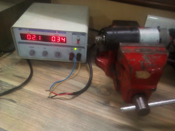
Observations
Here P = Power
V = voltage
I = Current