Week 10 - Input devices
Assignment
Measure something: add a sensor to a microcontroller board that you have designed and read it.
The idea
I will make a board capable of connecting to sensors and receiving inputs, the sensor with which I want to experiment is the bmp280, this sensor is capable of measuring atmospheric pressure and temperature. I think it is more practical to make a powerful board that can be connected with different sensors (and actuators) that make a board with a single function, in addition to practical I see it more versatile and interesting.
The board that I will manufacture is the Fabduino, a newer version of the Fabkit, an Arduino-compatible board based on an ATMEGA382P microcontroller.
What is an Arduino?
Arduino is an open source hardware/software programming platform based around Atmel microcontrollers. Open source means that circuit schematics and source code of software used in designs is freely available and can be modified by enthusiasts. Arduino development boards with their analog and digital, inputs and outputs. Input and output signals are made available on the Arduino board using rows of female connectors into which individual leads or single in line (SIL) connectors can be plugged.
To make this board I have reviewed some projects. check this:
What barometric sensor?
Pressure is defined as force per unit area applied to a surface in a direction perpendicular to the surface. Barometric pressure or atmospheric pressure, is the force per unit area exerted on Earth’s surface by the mass of air overlying the surface. High pressure indicates more atmospheric air mass over a given area, whereas, low pressure indicates less atmospheric air mass. Barometric pressure is strongly dependent on elevation, and decreases as elevation increases, due to less overlying air above the surface (shorter column of air) at higher elevations.
Barometric pressure is measured using a barometer. Aneroid (without liquid) barometers are often electronic and typically use capacitive elements to sensor pressure, with the major advantage of capacitive sensing mechanisms being minimal temperature dependence. Capacitive sensing circuits output a voltage that is related to pressure via sensor-specific calibrations. Apogee Instruments Barometric Pressure Sensor is an aneroid barometer consisting of a silicon capacitive sensing element and signal processing circuitry mounted in a compact epoxy plastic/stainless steel housing, and lead wires to connect the sensor to a measurement device.
BMP180 Barometric Pressure/Temperature/Altitude Sensor fron adafruit
The board
Fabduino

I will upgrade the Fabduino board, I will add a 2.1mm jack to power the board with batteries. In order to add the Jack it is necessary to put a regulator.
A voltage regulator is an electronic circuit that provides a stable DC voltage independent of the load current, temperature and AC line voltage variations.
A simple voltage/current regulator can be made from a resistor in series with a diode (or series of diodes). Due to the logarithmic shape of diode V-I curves, the voltage across the diode changes only slightly due to changes in current drawn or changes in the input. When precise voltage control and efficiency are not important, this design may be fine. Since the forward voltage of a diode is small, this kind of voltage regulator is only suitable for low voltage regulated output
How to calculate the regulator / Online calculator

Here the list of devices
For rhis board we will use a ATmega48. Datasheet

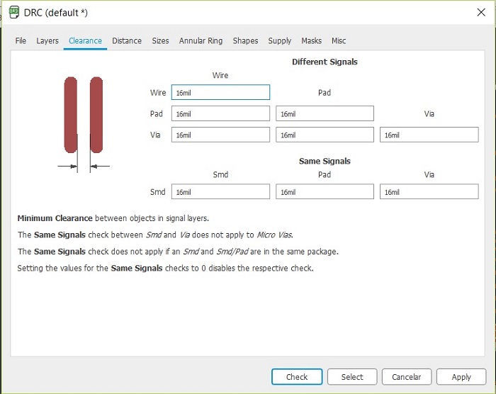
In this design i use welded pinheaders instead of drilling for pinning. Also i decide using a 0,02 tool for milling (traces) looking for more precision, this change it's reflected on the Eagle DRC setup window.


A text, just to see what happens.
The workflow for cutting out your board is as follows
- Cut out the traces using the 0,02mm endmill (traces file)
- Mill out the holes using the 0,7mm endmill (holes file)
- Cut out the board using the 0,7mm endmill

The text experiment failed, i will try again in other time, maybe changing the tool because this tool is in it's finals days. After this you should check continuity with a voltimeter to ensure there's no broken trace.
It has not been easy, the tracks are a bit mistreated since the milling bit was a bit worn.
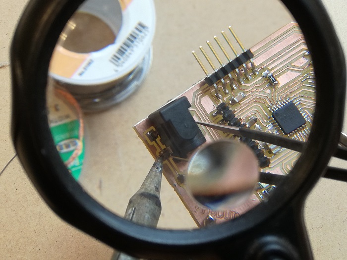
How to make the soldering. Check the Electronics Production assignment
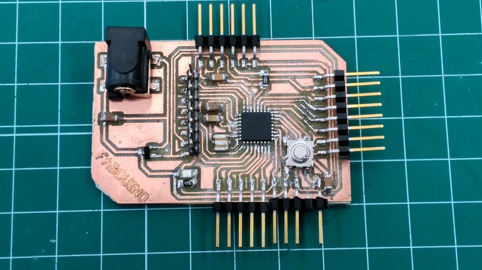
Finally the board is finished. You should check again the continuity.
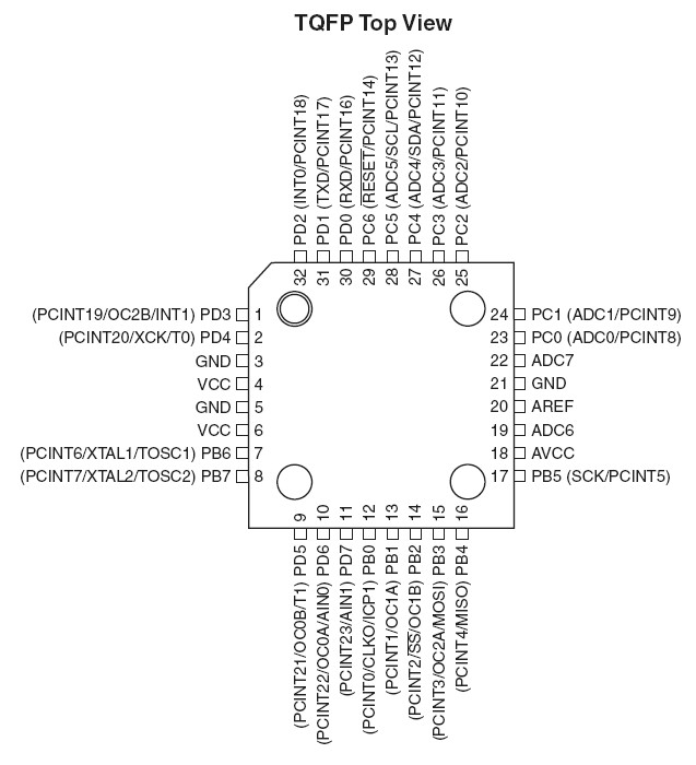
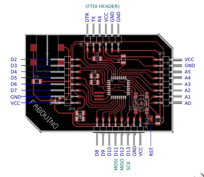
Fabduino Pinout
Fabduino Programming
I took a Tutorial from the Fabacademy 2015. and found that if I want to use it with the Arduino IDE, I need to add this text to the boards.txt files of my Arduino IDE installation.
//
fabduino.name=Fabkit/Fabduino w/ ATmega328 (internal clock)

fabduino.upload.protocol=stk500v1
fabduino.upload.maximum_size=14336
fabduino.upload.speed=19200

fabduino.bootloader.low_fuses=0xe2
fabduino.bootloader.high_fuses=0xdd
fabduino.bootloader.extended_fuses=0x00
fabduino.bootloader.path=arduino:atmega
fabduino.bootloader.file=atmega/ATmegaBOOT_168_atmega328_pro_8MHz.hex
fabduino.bootloader.unlock_bits=0x3F
fabduino.bootloader.lock_bits=0x0F

fabduino.build.mcu=atmega328p
fabduino.build.f_cpu=8000000L

fabduino.build.core=arduino:arduino
fabduino.build.variant=arduino:standard

fabduino.upload.tool=arduino:avrdude
fabduino.bootloader.tool=arduino:avrdude
The tutorial explains that the Arduino IDE should be the v.1.6, I try using a newer version and... it didn't work, I spend time checking connections, solders and code until you reread the tutorial and do it with the IDE version that was proposed

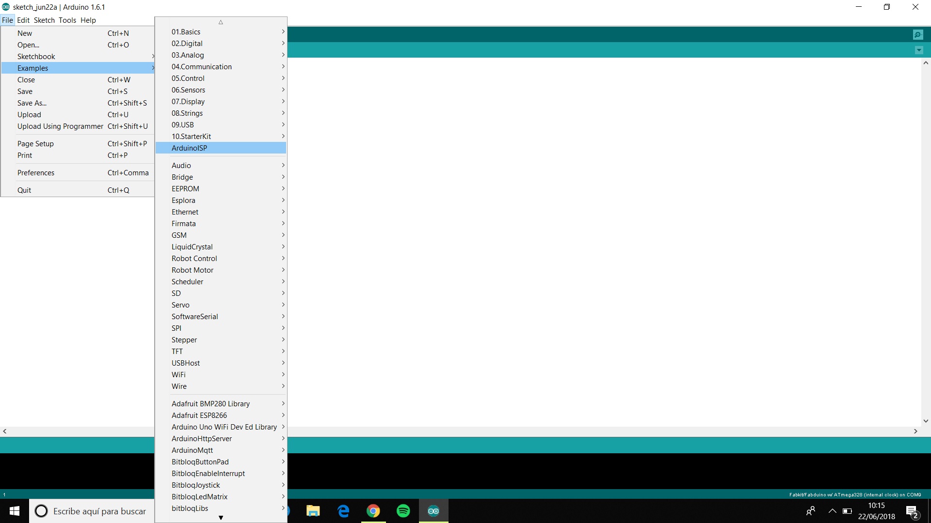
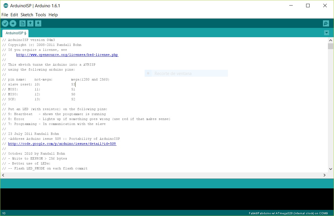
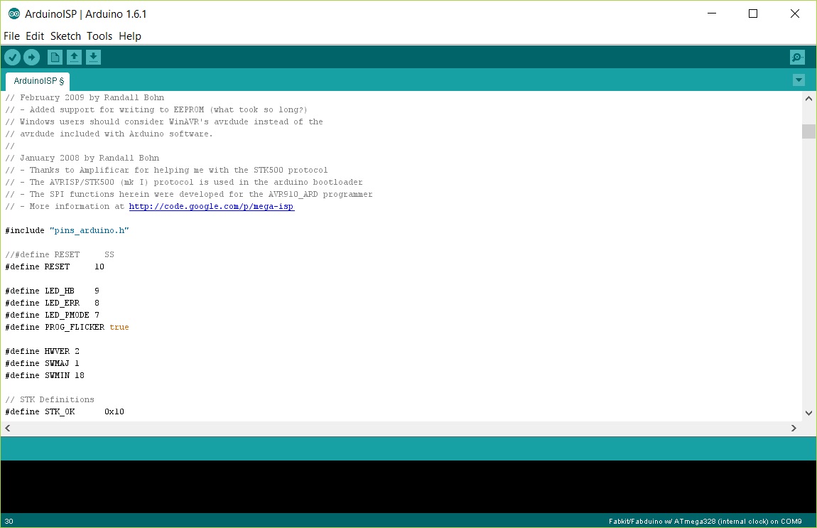
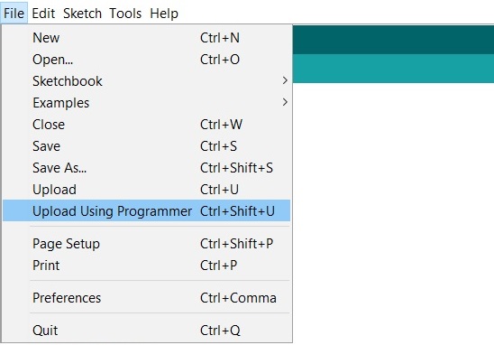
I used an arduino as an ISP to program the board. Follow the next steps.


The Sensor
bmp280 sensor
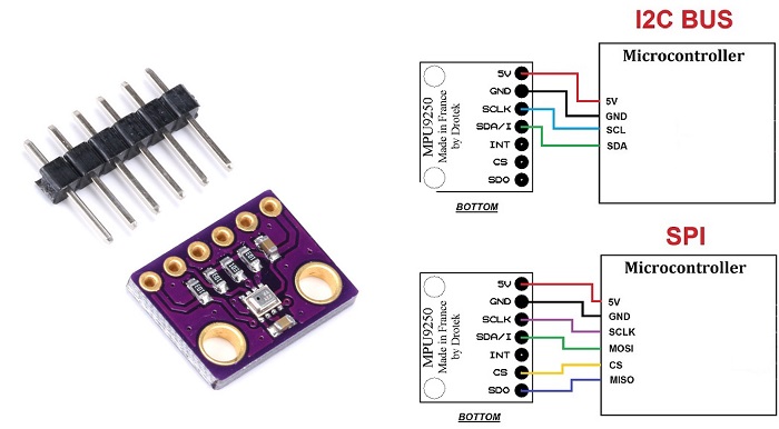
The BMP280 is an absolute barometric pressure sensor especially designed for mobile applications. The sensor module is housed in an extremely compact 8-pin metal-lid LGA package with a footprint of only 2.0x2.5mm2 and 0.95mm package height. Its small dimensions and low power consumption of 2.7µA@1Hz allow the implementation in battery-driven devices such as mobile phones, GPS modules or watches. It supports two types of communication: I2C and SPI.
More infoWiring

Wiring for SPI protocol

Add library to Arduino\libraries folder
Click 'sketch\Include Library\add.ZIP Library

Find Adafruit_BMP280 under BMP208\Arduino code BMP280\Library, click Open to add it

double-click BMP280_SPI.ino under BMP280\Arduino code BMP280\Code\BMP280_SPI to open it.
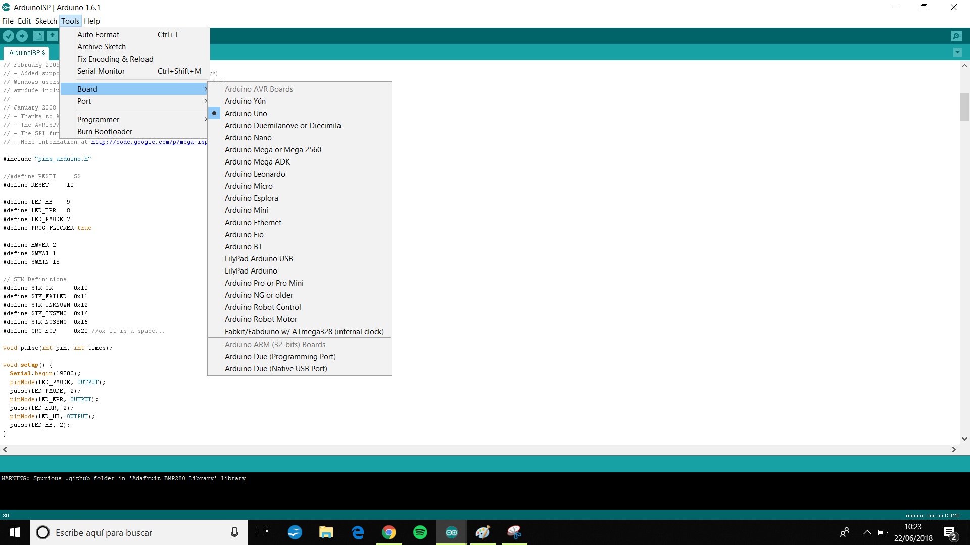
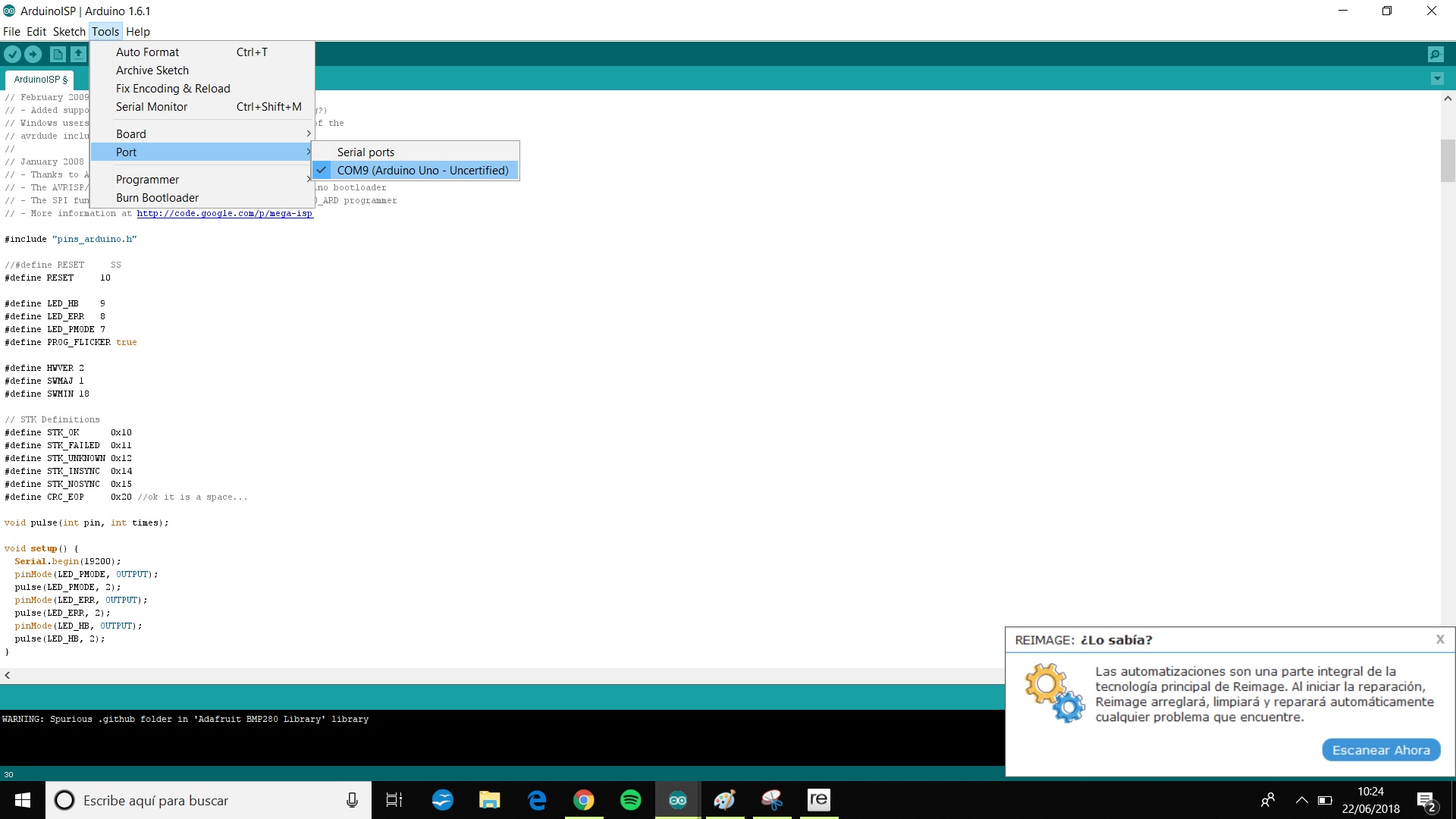
After choosing the correct board and port, upload the code to the board.
Open the serial monitor, you will see the figures of the temperature, the air pressure and the sea-level altitude.
Code
I have decided to program in SPI protocol, there are some advantages and disadvantages, here a sinopsis about it. More info

//

#include
#include
#include
#include

#define BMP_SCK 13
#define BMP_MISO 12
#define BMP_MOSI 11
#define BMP_CS 10

//Adafruit_BMP280 bmp; // I2C
Adafruit_BMP280 bmp(BMP_CS); // hardware SPI
//Adafruit_BMP280 bmp(BMP_CS, BMP_MOSI, BMP_MISO,  BMP_SCK);

void setup() {
  Serial.begin(9600);
  Serial.println(F("BMP280 test"));

  if (!bmp.begin()) {
    Serial.println(F("Could not find a valid BMP280 sensor, check wiring!"));
    while (1);
  }
}

void loop() {
    Serial.print(F("Temperature = "));
    Serial.print(bmp.readTemperature());
    Serial.println(" *C");

    Serial.print(F("Pressure = "));
    Serial.print(bmp.readPressure());
    Serial.println(" Pa");

    Serial.print(F("Approx altitude = "));
    Serial.print(bmp.readAltitude(1013.25)); // this should be adjusted to your local forcase
    Serial.println(" m");

    Serial.println();
    delay(2000);
In order to work with the bmp280 sensor, program in SPI protocol, and visualize the result of the input data in the Serial monitor we will need some libraries
adafruit_bmp280.h, wire.h, SPI.h and adafruit_sensor.h
Once you execute the program you have to open the 'serial monitor' and you should start viewing this.
