laser

Circuit Board Design

For this assigment designed our PCB. For that we had to learned how to use the software Eagle. The first step was to add the Fab library to have the same components in eagle as the one we have in the lab. Firt i download the libary, second i put inside the folder in the eagle folder . Than i open eagle clink on library, manage library , browse the new one and than open it.
laser
After i started to add the components that i need in my design. I copy the hello-world and add 2 buttons and one LED, and also the 3 resistor for it.


laser

After i add all the components i add a connection and renaming ti i was able to connect them.


laser

After it i open the part of the eagle to generate the design of the board. I put all the components on the place and with the comand "route" i drew the tracks to connect it. It's usully the trick part when the person have to design or redesig a noard.


laser

After it was done i checked in the errors with the command "DRC" then i fixed it. All the clearences should be 16 mil so it's sure will not have major issues on the milling.
laser laser

laser

With the board ready i exported it as a PNG and put it in the FabModules and generate the RML to mill my board. First as a imput i add the png file, after as a outputi chose Roland mill (.rml) , and for the process the PCB traces (1/64) or outline (1/32). For the machine i chose SRM-20 and i kept all the other settings as it comes in the default, press calculate to check the traces and press save to generate the file.
laser
I had some issues because when i was cutting the outside my board move but i had to stop the machine and break it with my hand. after all i soldered it and i test (with the voltmeter and with arduino programing) to see if all components were working.


laser

laser

It was working , i was able to program it with arduinos library, using the button example for it. It was my first interaction with arduino and i learned the basic to program digital pins. Here is the file.


laser
laser

Test Equipment PCB

Another part of this week’s assignment was use the test equipment in your lab to observe the operation of a microcontroller circuit board. First i test the led. With this test is possible to see the colour of the led and the sides of it (ground and voltage).


laser

Te second test that i made was to measured resistance of the resistor.
laser

At the end i mesured the voltage. laser

Basic Concepts of Electronics

Ohm´s Laws:

It is the basic law of electricity where the current through an ideal conductor is proportional to voltage.


laser
Current:

Electrons flow.

Ampere (I):

how many electrons flown through for a certain point per second.

Voltage (volts):

Electric pressure which push current through an electric circuit

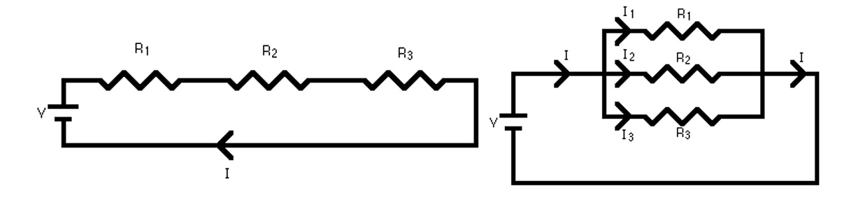
Resistor (R):

It contains the flow of the electric in a controlled way

Arrangement of resistor:

It is a combination of series and/or parallel resistors.

laser
Capacitor:

It keep an AC current stable.

AC current:

Electric current which change the direction with the time.

DC current:

Electric current which the direction is continually.

Crystal:

Timer/ Clock

Resonator:

It is a crystal with a capacitor inside

Transistor:

Electrical switch or amplificatory of the voltage.

LED:

It uses diode to emits lights

Microcontroller:

It is a small computer which control all the board

High/low (=1/0):

refer to the physical voltage levels (high – 5V to 3V , Low – 1.5V to 0V)

Button:

it controls the open-ness or closed-ness of an electric circuit

BUTTON – IMPUT – MICROCONTROLLER- OUTPUT - LED