Final Video

Idea
I started get in touch with the education area when I decided to do my undergrad final project about class rooms. I started to learn more and more about the active learning that’s is a type of learning where the student active and nor just the receiver of the information. One of the reasons I understand the importance of this kind of learning was because of the Ted Talk of Sir Ken Robinson about “Do schools kill creativity?”:
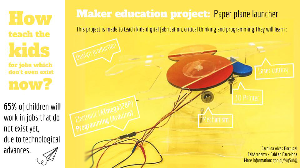
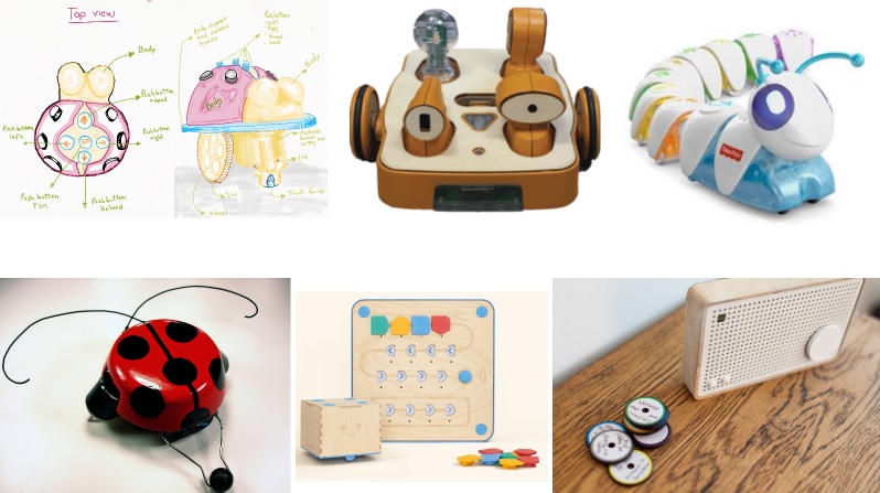
My idea for the final project still not totaly define but I know I want to do something to help kids learn basic of mechanics and electronics. For a while i was planning to build a robot to teach small kids basic of programing but found a thousands of other project really similar with what i was thinking.
Now my ideia is a toy that the kids can build and not just play with it. I talk with a few people who work with maker education and they told me
the kids are always interested in build something which fly. Because i wanted to make something simple enough to be build for a kid and i alredy work in são paulo with a
project similiar to it i decided to build a paper airplane launcher.
So i decided to make a project that can be use for the kids of the Fab Lab Barcelona.
For my final project i will use one servo motor and two dc motor, for the firsttry i will use a button as a imput but if i had time enough i wanna use a noise sensor. I will make the electronics work first than i will do my own design. I choose to do this way because i got in FabAcademy to learn more about electronics and programing than the design part.

Development
Schedule
i started to do my final project late. I did it in the last 2 week. I decided to start and focus with the programming and eletronic part. After it was all done i started to designed based on what i had before.
Electronics
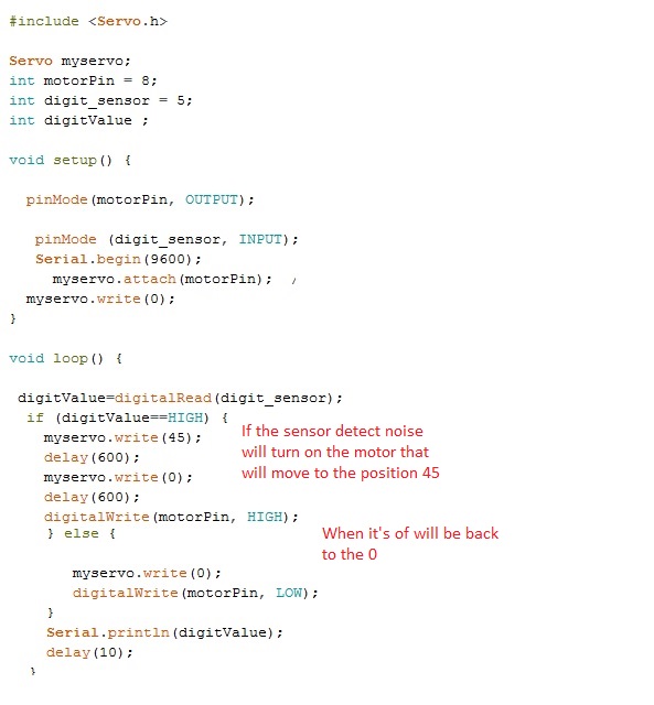
I started started to study how the motor with a arduino would work. I used an arduino and a the servo library and the button example to program the motors. It worked pretty well.
After that i connected the noise sensor to the board to try. For that i conect one cable in a digital pin, one in the ground, and one in the votage. I used Sound Detection Sensor Tutorial for the coding and better undertanding of the sensor.
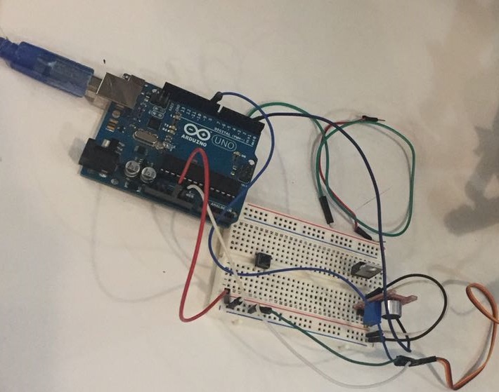
it was hard to make it work but after i get the right code and with the right calibration, it worked and it attivate the sever mottor attach to it. After i made my board, i used a satshakit tutorial. The reason i chose this board is for two reason:
1) the possibility of improvement on the project. So if all the free pins it can be connect more motor without a new board.
2) The possibility of usig iton other project. It is a education project so i would be interresting if the board could be use for other educational projects on the same place withou have to mill again and again.
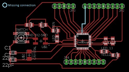
So i followed the tutorial to make the board on eagle. The first try i put the wrong microcontroller and it end up not milling correct.
I changed the button as a normal button and not a reset one in case my imput didn't work. I end up forgeting to put a pin just for the reset pin but i was able to program it doing the reset it manually (touching the pin with the cable).
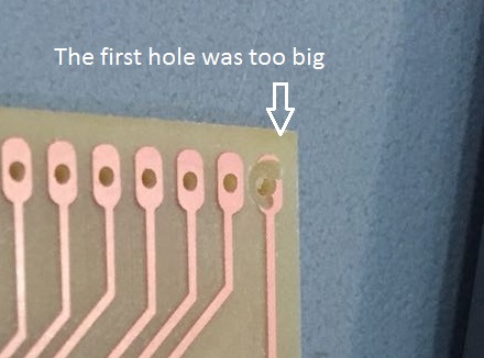
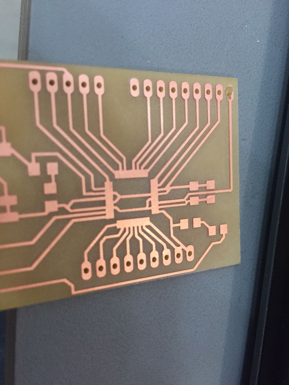
After all ready one the eagle, exported to a png. To make the holes i had to use the photoshop. For the first try i use black background to white hole, it made the holes to big and i had to invert it on fab module. I used the 1/32 tool to do it. With all the files ready i milled the board again.
I started soldering the Atmega328p , to do it i used flux to fix better it on the board. To learn hor to use i followed this tutorial:
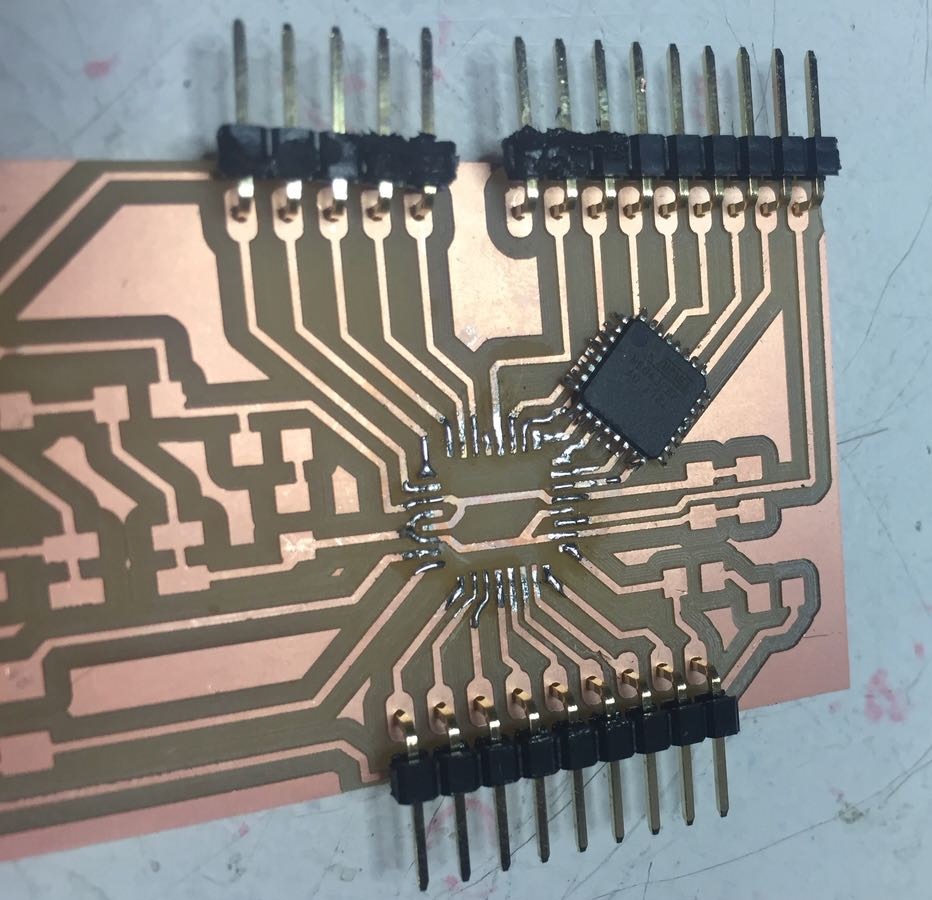
After i soldered i test the pins and i realise the VCC and the ground were connect but was not the pins. So looking carefull the picture and was a really small connection
under the microcontroller because of the milling. So i had to unsolder it and break the connection. After i resold it and soldered all the rest. I test again and i had to change a led.
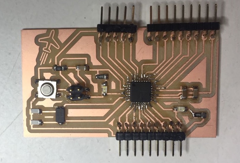
After all, i was finaly able to make my board.
With the board ready i had to bootload it, two of my classmates had the same problem to bootload the board so i just followed this two tutorial to do it with a arduino:
- Nick Gammon
With the help the tutorial i was able to bootload without much problem. After that i connect the FTDI cable to send the code.
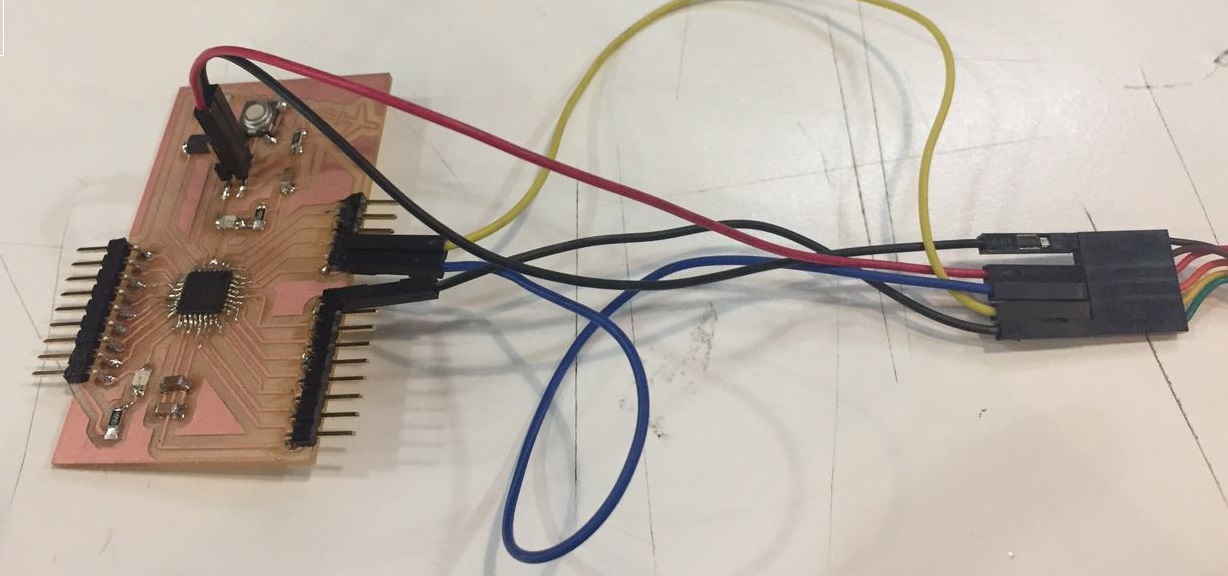
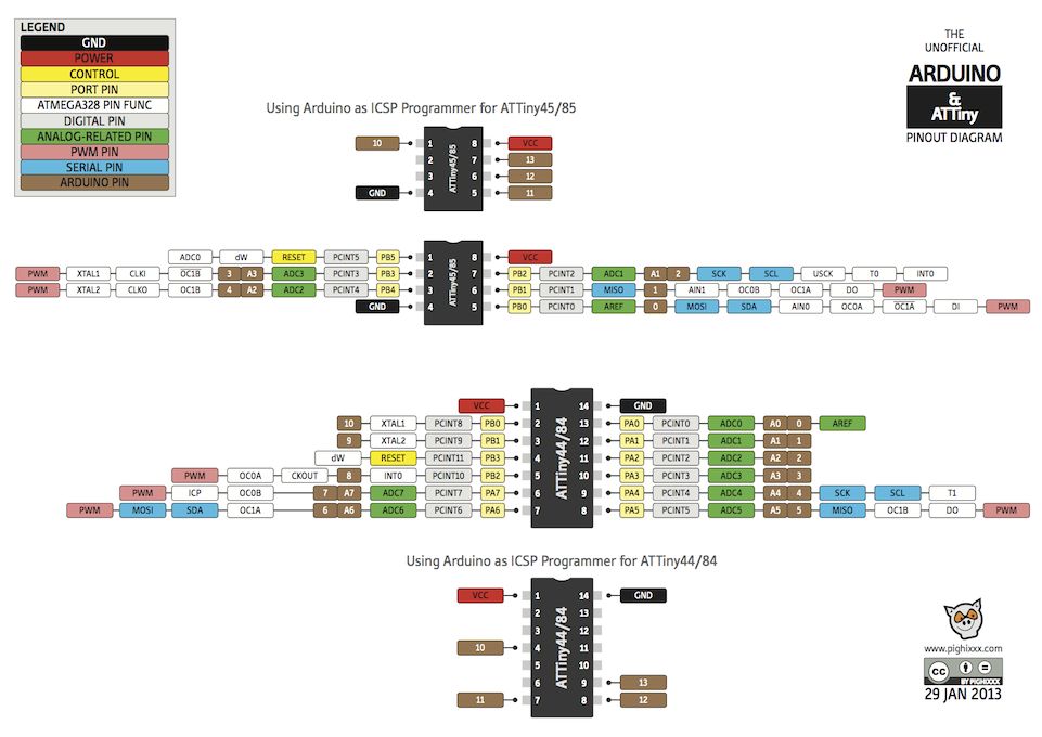
I was able to run the same code and make the sensor work! First i made a schematic how to conncet the FTDA cable to the board to send the code:
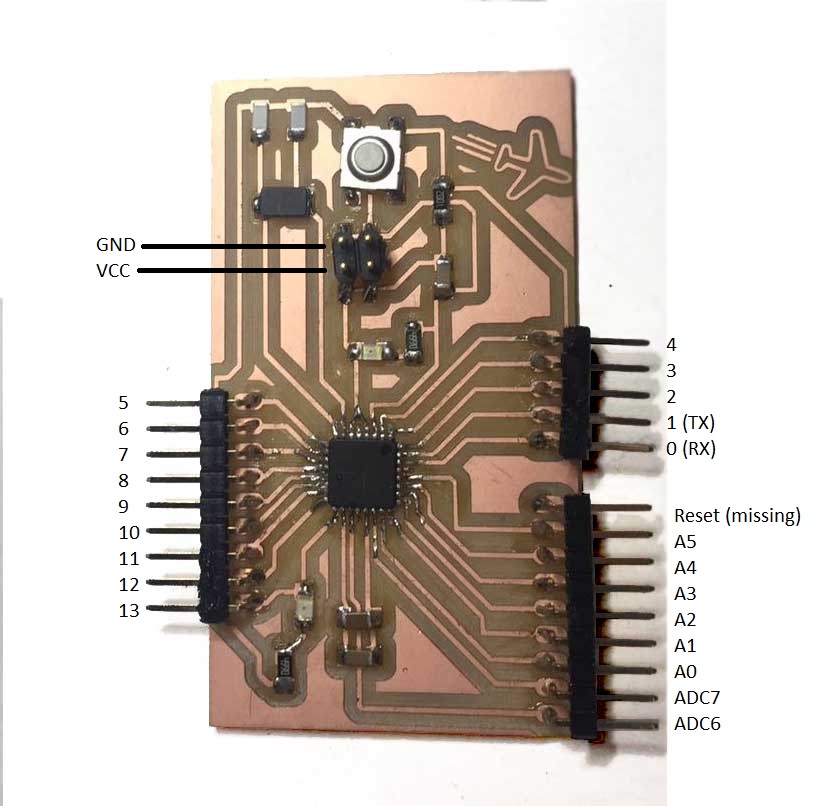
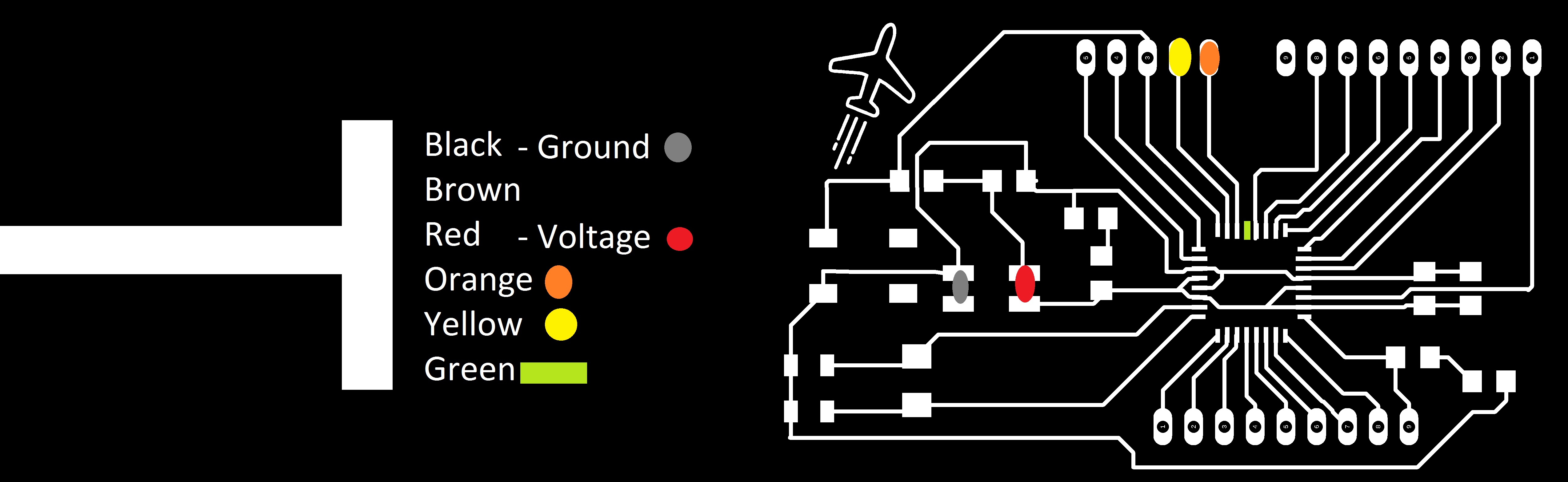
To conect the sensor and the motor to the board i made this schematic to know with pin is corresponds with the arduino one.
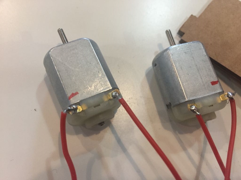
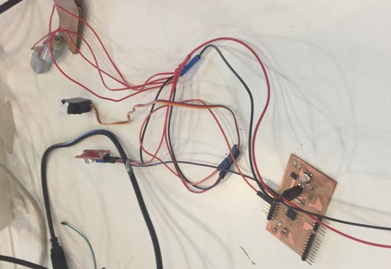
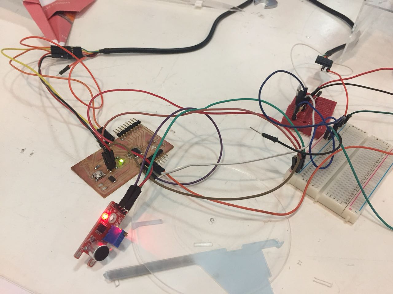
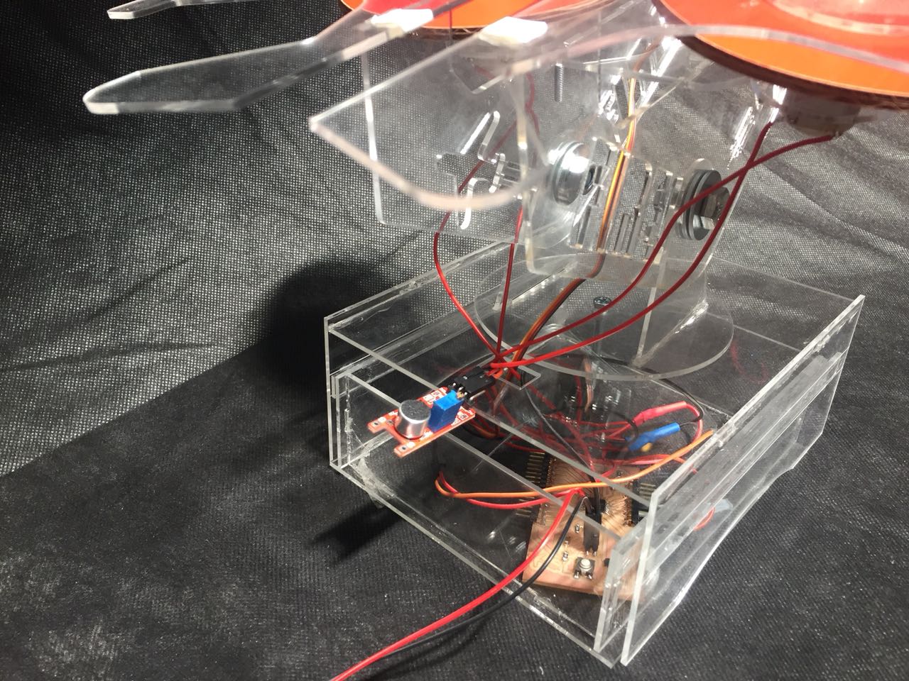
I had to do the conectio between the coltage and the motor. i had to make sure that i connect the DC motor in opposite ways to each one spins in the opposite direction. I solder all the cables toggether, to protect the soldering i used heat shrink tube assortment and involve it. After that i connect all the system, the servo , the 2 DC and the sensor. It work in the first try.
After i made all my design , i when back to put all together but when i turned on the whole system on. But the motor with the wheels were getting too much of the energy and making the sensor and the servor motor not to work.
To fix that i had to put another source of power. After i put the DC motors separate i would make it work.
Because all the noise of the DC motors the sensetivity of the sensor had tio be really high so than the person or the noise has to be much more laugh. It was a bit annoying but didn't affect directly the function of the project but i could do the first improvement of it.
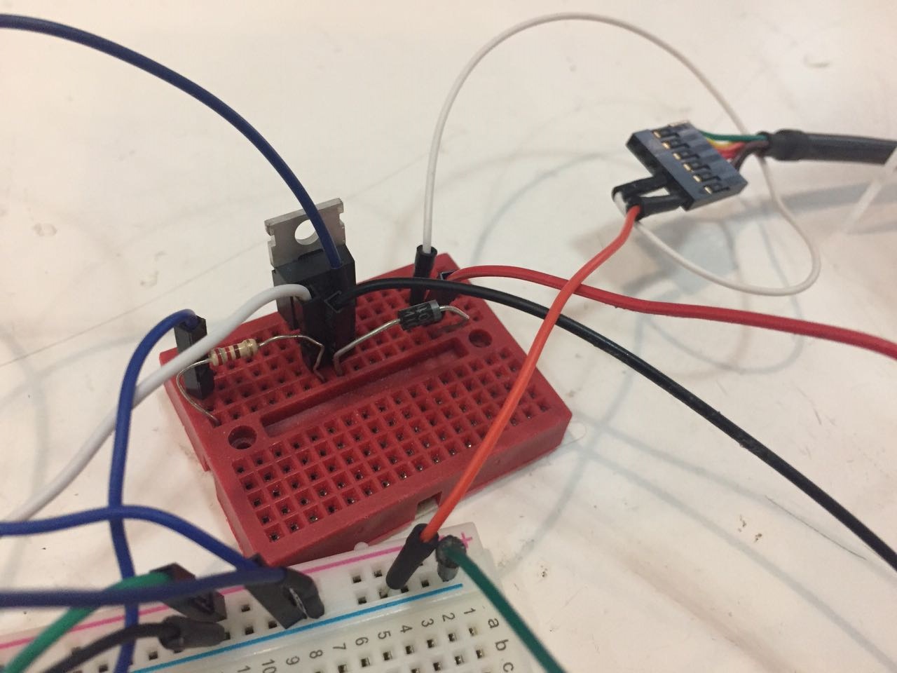
So i decided to connect a mosfet to the system.To learn how to use it i followed this tutorial . i could control the dc motor just turn on after the sensor is active.
Design
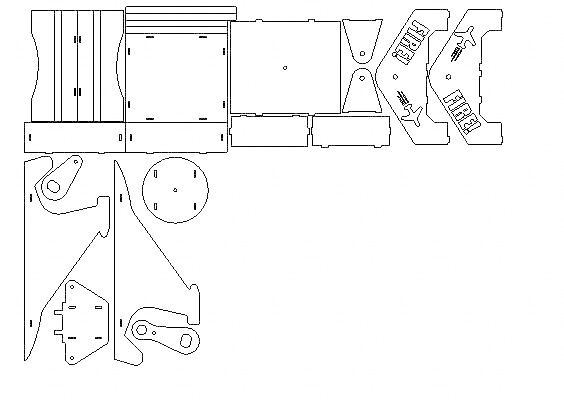
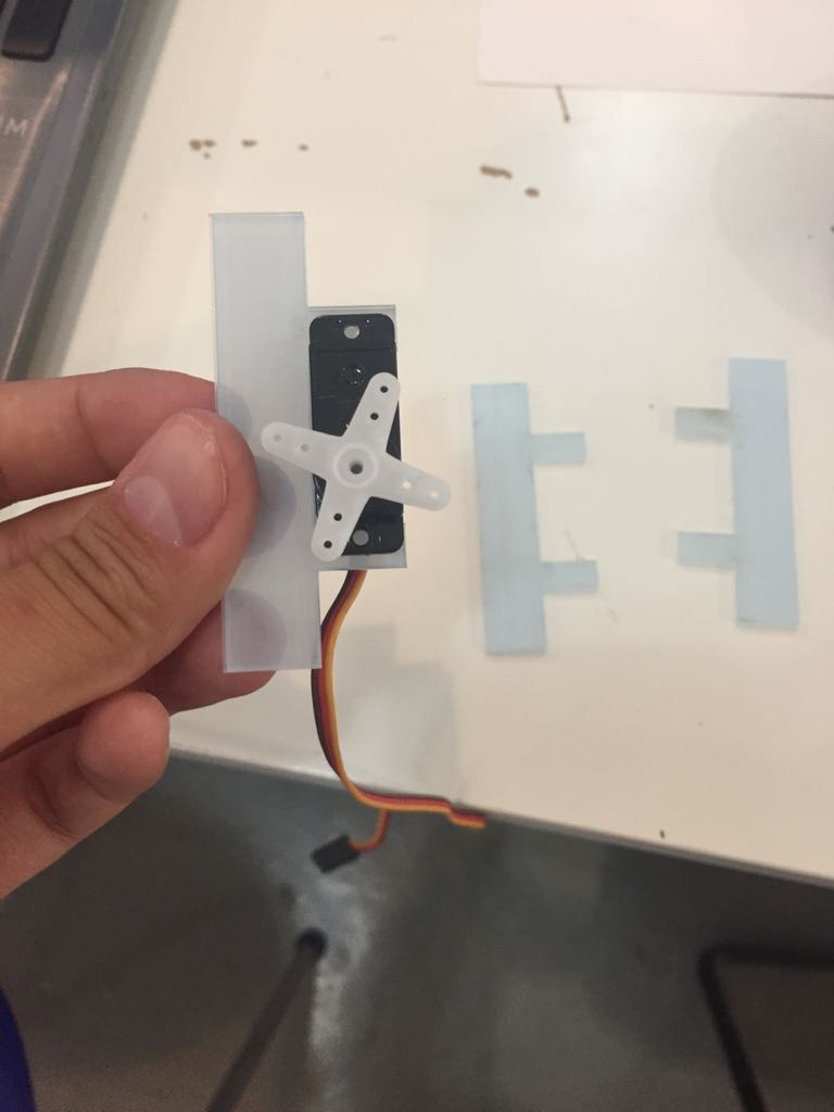
The focus of my final project was not the design. I got in the FabAcademy to learn more about the electronics and programming. I based a lot my design on the previous project. I designed it on rhino 2D , and to make it right i have to test a few times in cardboar. I had to redo the box and the piece where it the motors are fixed.

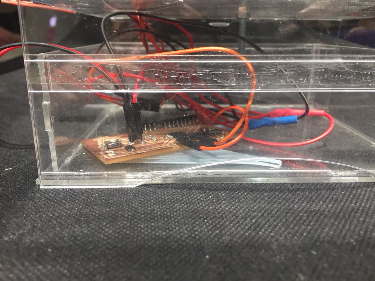
I made some modification as a bit more with Airplane details as the top part and the side parts with "FIRE". I also inclued a box under the project to keep the eletronic part together. I choose another material, i choose acrylic to be easier to visualize all the macanical and the eletronic.After figure all the design test and choose the best design for my project. But before cuttin in the final material i run a feel test to know the size of the holes and suports for the acrylic.
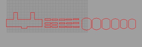
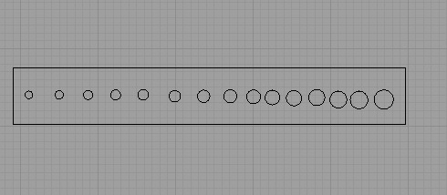
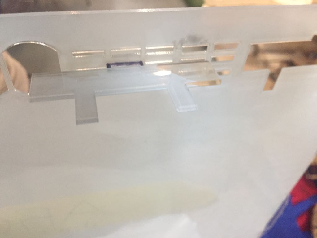
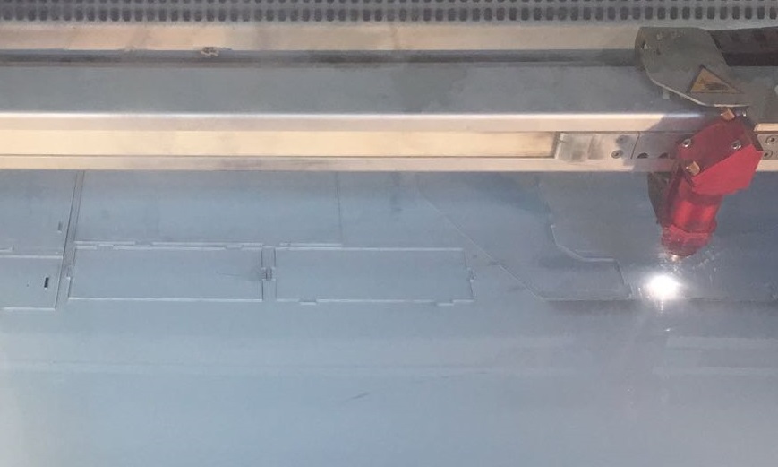
With all test ready , i went back to review the design and make the modification that it needed. After all done i went to laser cut and cut it (70,07,2000).
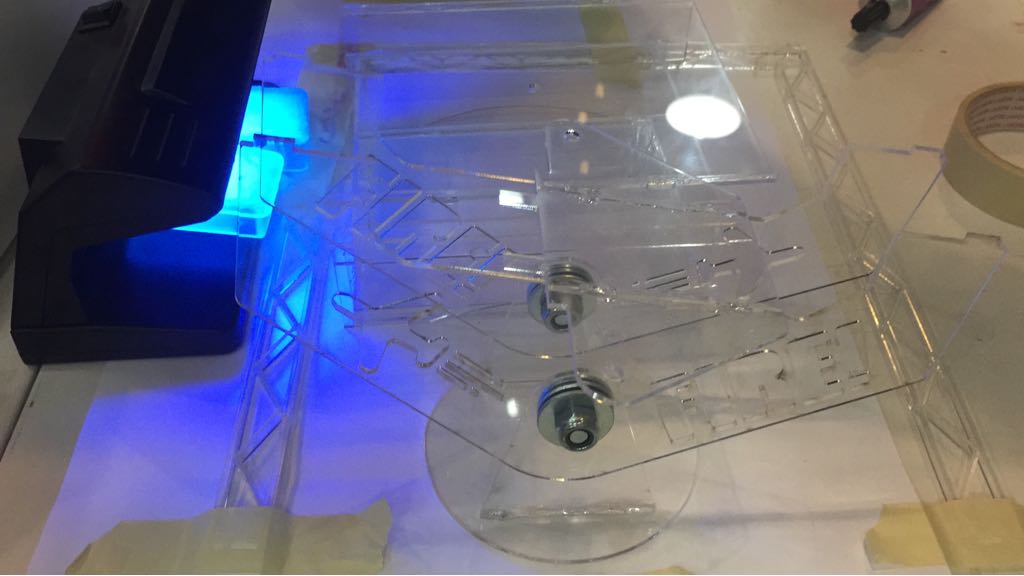
After all cut i start to put all together, i notice it was a bit lose because i didn't considerated the plastic outside would make differnce on the thickness of the material. So i had to glue it to make better. To glue it i use a especial glue for acrylic and after put or in the sun or in the UV light.
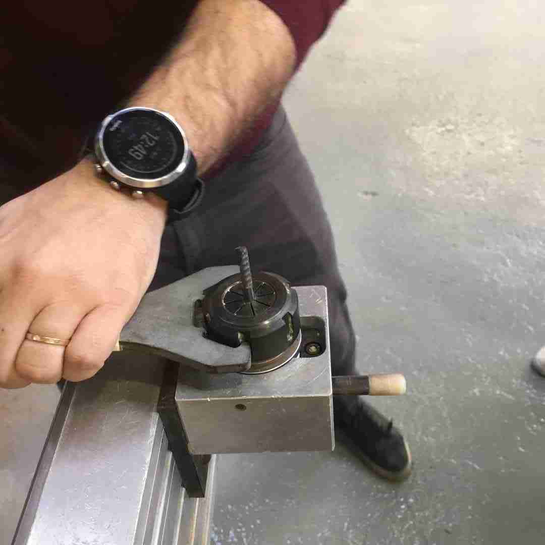
Other part that can have movment i put together with bolts and nuts. I had a problem in this part becuse i forgot to test on hole and it was too tight. I tried to use drilling machine , but i end up breaking on piece and i had to redo it. After problem that i had was that i glue on pice in the wrong direction so i had to redo all the top structure.
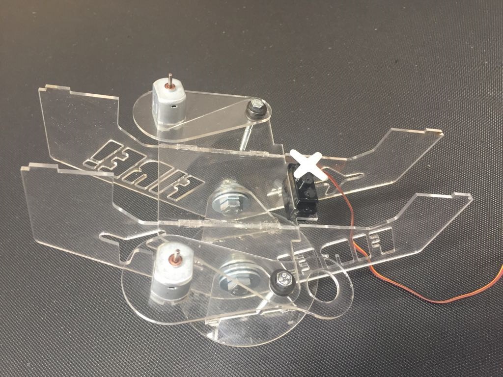
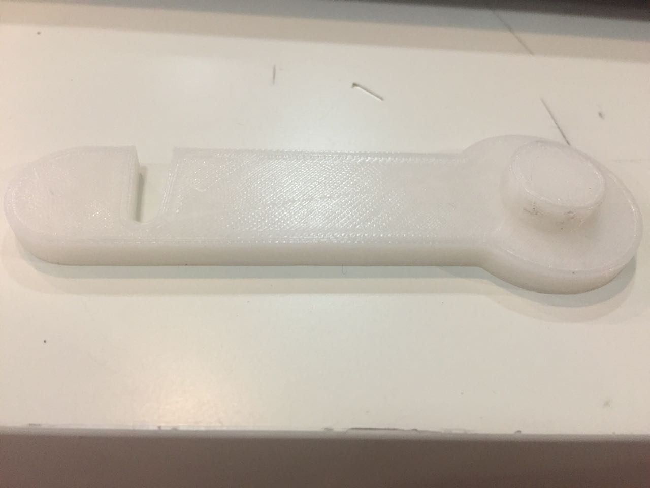
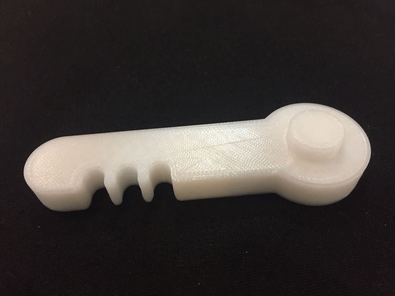
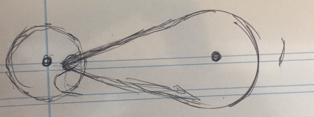
I also had to design a 3D pice and i made the decision on use for part of the mechanism. I design 3 different pices on rhino and on the 3 try i could get the movment that i wanted. To get the rigth pice i used the first pice and made test with it, drawing the moviment in a paper.
After putting all together this is the final result:
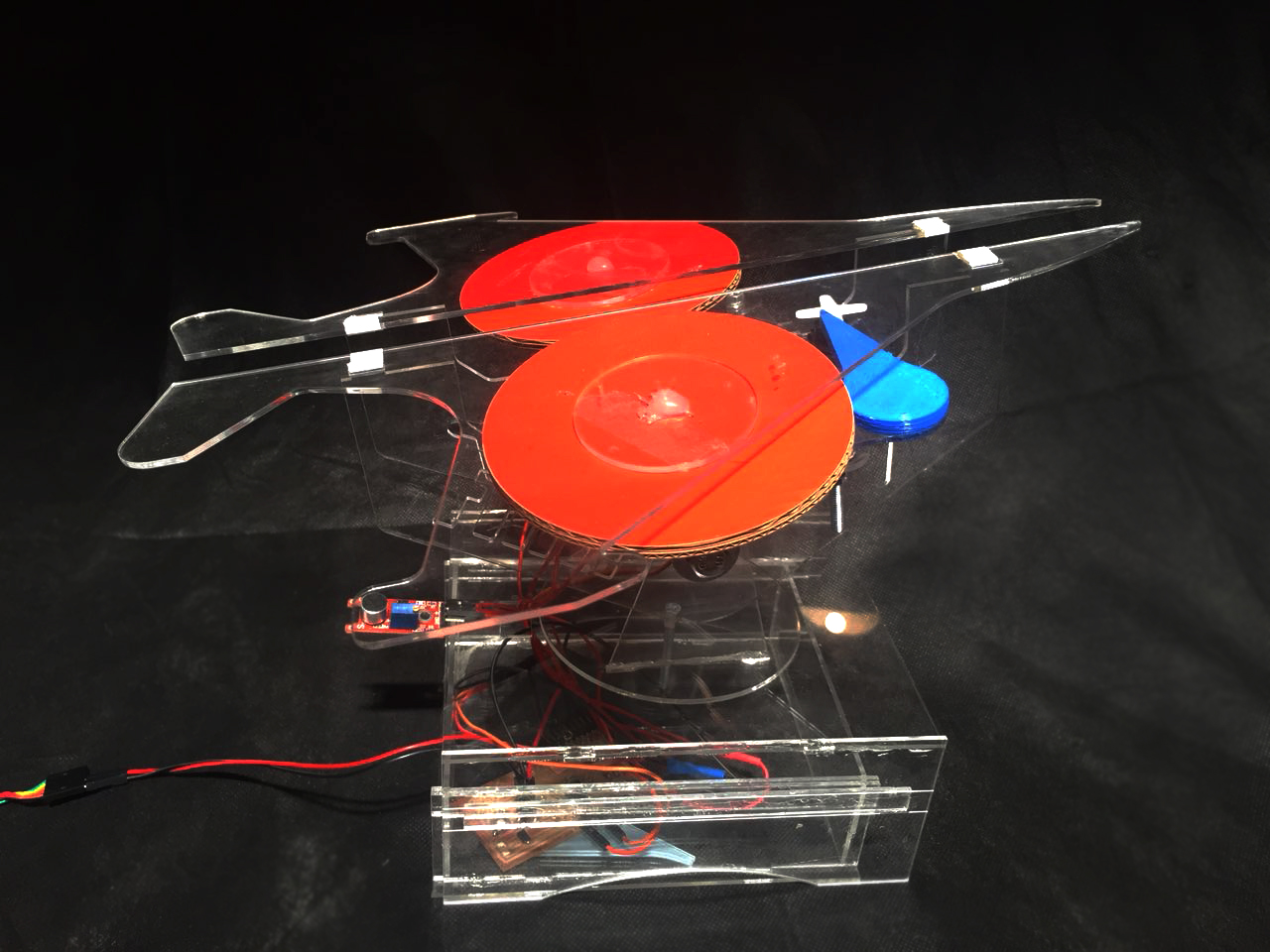
And this is it working:
Material
I use 2mm acrilic, cardboard, cables, PLA 3mm, cables, Laminated Copper Sheet, ATmega328 (and other electronics devices), one FTDY cable, one noise sensor.
ImprovementMy project can have at least to more mottors, one to control the angles and one to control the rotation. Another improvement would do it's use a thicker acrylic just to give more stability.
Here is the file.