laser

Computer-controlled cutting


This week we had a group assignment that consist in characterize your lasercutter, making lasercutter test part(s), making test part(s) that vary cutting settings and dimensions. My group was Ilias, Andre, Michael Maximilian Eve There are two laser cutting machines that can be used at the moment at FabLab BCN. A 8010 Trotec Speedy 100 / R that is 100x60cm (that is the one we used for this test): carro The small one, 8010 Trotec Speedy 100 / R, that handles pieces with maximum size of 60x30cm: carro

laser

There are some preparation steps to do for using the machines:
Choose and measure your printing material and cut it manually to fit machines if needed;
Check under honeycomb for material leftovers. If so, clean them otherwise they might catch fire;
Remember to turn on vacuum system (ask instructor to do so), so that fumes get expelled outside;
Turn on machine and place your material on the honeycomb surface making sure it’s as flat as possible. If not you can tru masking tape or cut the piece in smaller parts;
Focus the laser. We are using a manual measurement tool/guide and move up the plate until the guide falls.
Move machine laser manually (using the touchpad) to a “0-0” origin point on your material;
Close the lid;

At this point we are ready to set up our job on the computer
Import your files from the shared Iaac Cloud drive;
With Rhino setup the printing window so that it contains your drawing and print your design;
At this point the Trotec Job control windows will open;
Connect to the laser machine () to find your laser origin and place your desing under it;
From “setting” adjust the laser power/speed/frequency for each color that you’re printing. Also select either “cut” or “raster” (this is good for engraving);
From the menu select the option “optimize vector order” to optimize/reduce the path that the laser will follow. This can save a lot of time for big pieces;
Print you job! And check that the cutter is executing it properly.

laser
We started using some plywood because we thought it might be more relevant for our group projects than cardboard. I end up using cardboard in my personal week project to test it.
Our first try went on fire. So we had to stop the machine.Initially we used the “kerf” desing but was taking to much time. We learned that it is important to have a very simple design and try variations of power, speed, and pulse rate.
Also it is important to have a clear strategy to explore the values. On the Trotec 400 we found that the optimal values for a 3mm plywood is the following (80 1.7 1000).

We also found that is important to keep at hand few sample test files in Rhino: Prepare and improve few sample for testing every new materials and every laser cutter condition! Because our lab is using Rhino to connect to the laser cutters it is useful to have those files ready in Rhino format. At the end of the session I ended up creating some following sample files that could be reused for this.
laser
On the next day we wanted to try engraving to print images as different shades of colour.
The important difference is to select Engrave in the material settings panel of the cutter Job Control tool.
I created a sample file with different colour to try different power / frequency settings. In the example below we set a base line for black; changed power along red-blue-green; changed frequency along magenta-cyan-yellow.
After different trials we saw confusing results (eg. 800hz is darker than 600hz, but ) realised that the different colours were translated during the printing step in shades of gray, and after this the different material-color setting were ignored. We found optimal setting for “Red” colour

Power - Speed - PPI/Hz
100 - 100 - 1000

Which translates more or less to the following setting for “Black” colour

arduino

Power - Speed - PPI/Hz
70 - 100 - 1000
Finally we the setting above we tried to print a bitmap image.

arduino
laser

Parametric modelling allows the person to modify an entire design by changing only one attributes. For that I had to use the Grasshopper, that is a plugging to make the Rhino parametric. In the beginning I was trying to parametrise a design that I created in Rhino, but after a lot of time wasted I decide to design it direct on the Grasshopper. My main sourse was the class they gave us in Fab Lab Barcelona. The idea of the grasshopper is instead to use the command and click on the screen to let the software let you know what you want to do, you use “blocks” and connect them to make your design. I first started with a simple shape, after I exploded and divided it. In this divisions I place a feel squares and connected it to when the first shape variate the squares keep the same.


laser

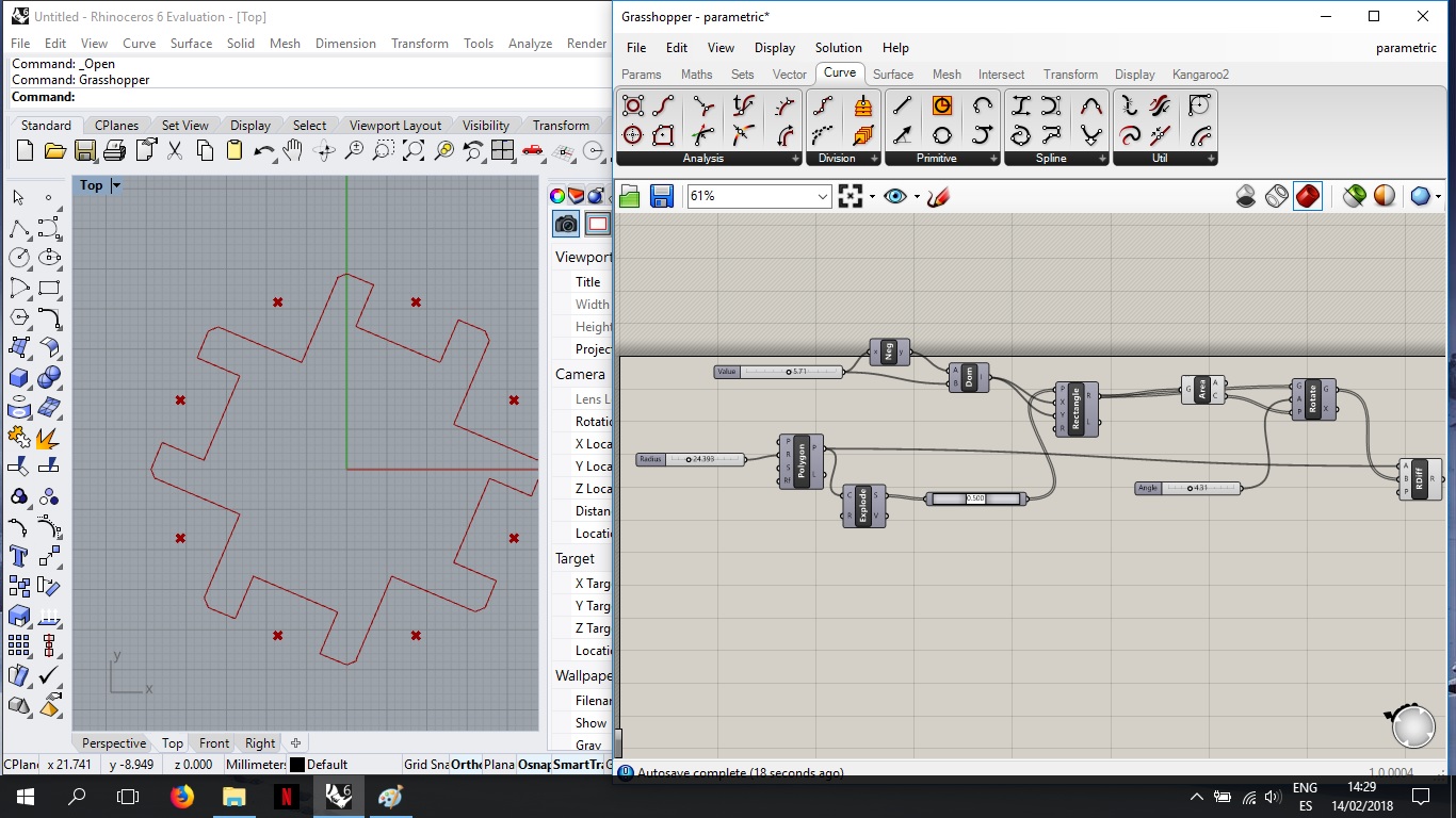
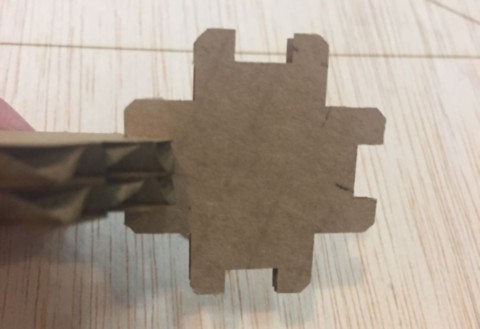
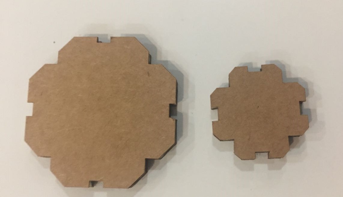
After it I set the size of the connection and baked it in varied sizes. I had a problem with the size of the connection because when I tried to cute it was double the size, i realise it was the mistake because i could i could fit 2 pices perfectly on one whole. So, I when back to the program and add a division on it. laser

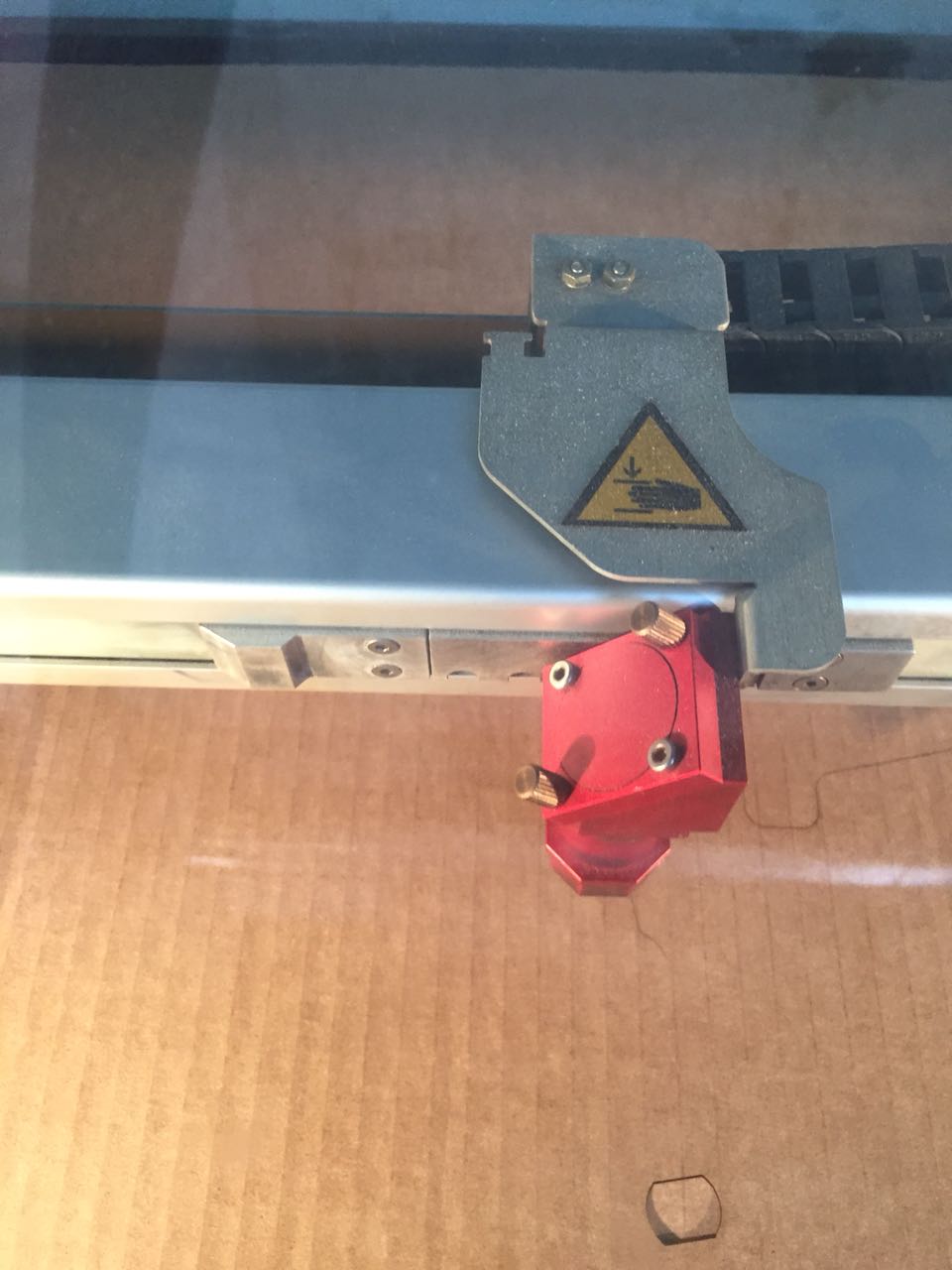
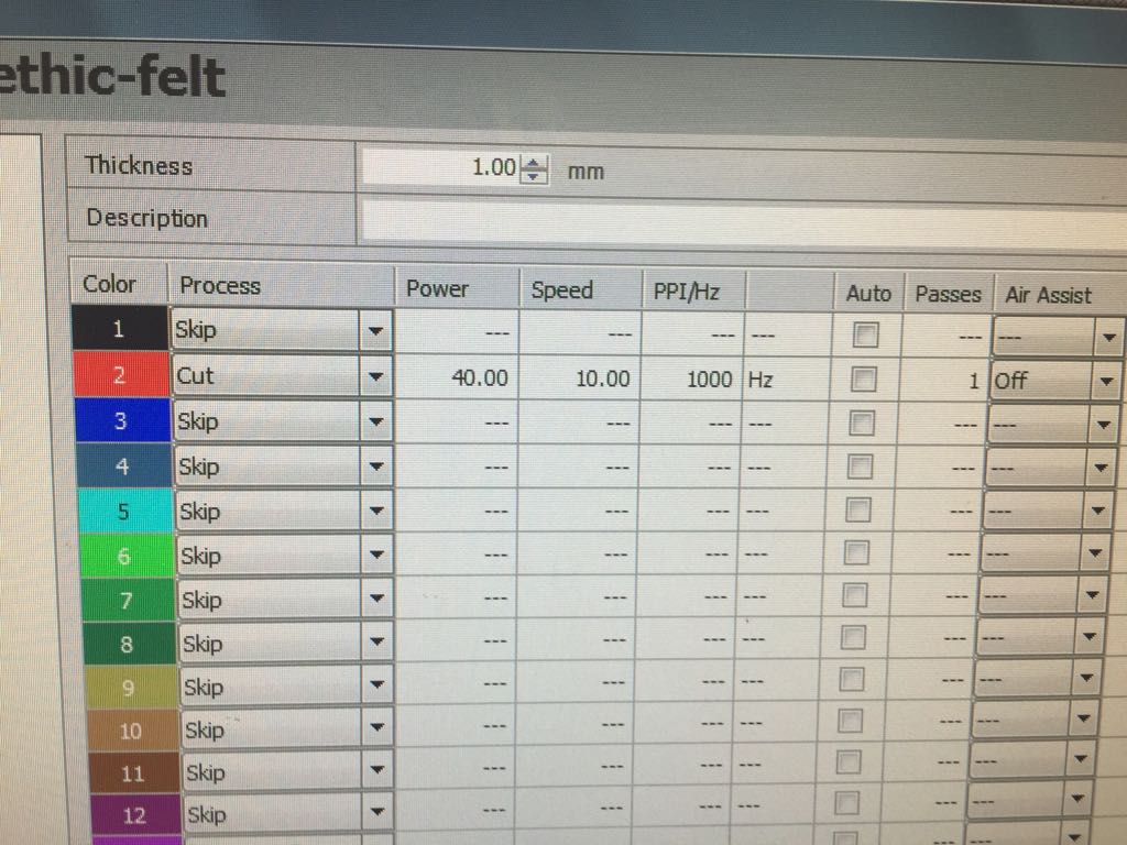
After check everything was right I run a few test to get in the righ parameters for cut car 3 mm the laser cut (30, 0.9 , 1000) and I cut it.

laser laser laser

i learned a bit on grasshopper but for the future i want to learn fusion 360 because it intrage better the 3D modeling with the parametric modeling. Here is the file.


laser

Vinyl Cutting

For this part of the week assignment we didn´t have a specific project, we just had to learn how to use the tool. The first step was to design the image that I wanted to be cut on the sheet. For that I used a image from the internet as a based for the vector that i wanted.

laser
I paste a jpg on the software and used the "line" tool to draw curves and straight lines overlapping the image.
laser
laser laser
After I copy the draw to the vinyl cutter’s software adapted the size of it. On the Roland GS-24 vinyl cutter (584mm) I put the piece of vinyl on it, set the machine for piece and teste it pressing "test" on the screen. To set i had to select the type of material “ROLL”, “PIECE” or “EDGE”, i used the piece and the machine measure the sice of it. To cut i press "CUTTING", selec the right machine then "PRINT". After confirming that it was everting ok I initiated the cutting. To remove the image i use a tweezers and applied to my celphone case.
laser
It was the first time i used a vinyl cutter and i hope i can use it more to explere more its functions. Here is the file.