Input Devices
For this assigment i had to measure something, adding a sensor to a microcontroller board that i designed.
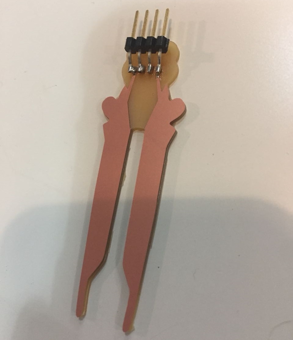
First, I decide to do a humidity sensor for kids.
My goal was the design to be a bit more attractive for kids be more interest on it. I based my ideia on a previous student project (Ranpura - 2016 ).
The first challenge was to design and understand how it would worked. To design i used photoshop and the Ranpura's png; modifying the shape of it. After doing it i milled it but i noticed i had a scale issue.
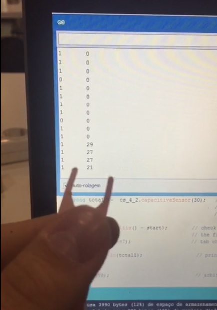
I went back to my design and i fixed it. With the board milled i soldered it. For better undertanding of the process i decide to test it first with a Arduino. I had a lot of trouble doing it.

After it, i used the Arduino examples to program it in a way the arduino could read it. After running the code i had to change the buttons status to LOW because the way i put the resistors. To get a more stable and clear data i had to change a few times the resistor.
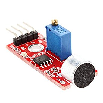
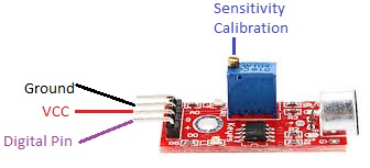
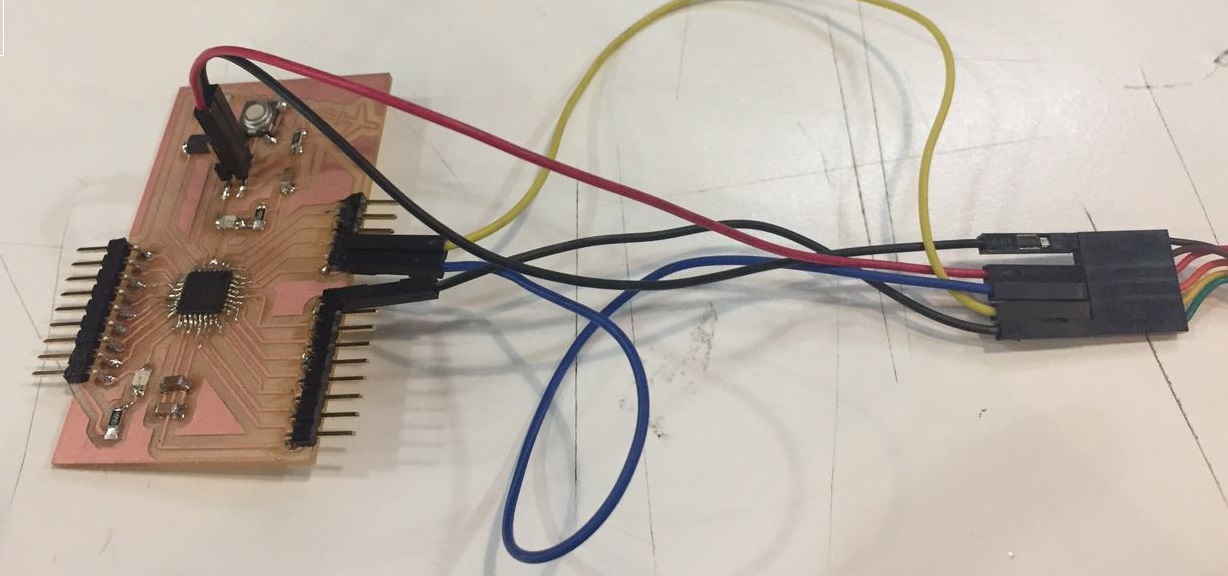
I end up giving up about that idea and started to do the input of my final project. It started to testing a noise sensor with arduino. For that i conect one cable in a digital pin, one in the ground,
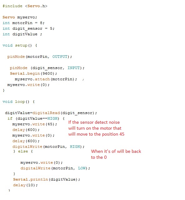
and one in the votage. I used Sound Detection Sensor Tutorial for the coding and better undertanding of the sensor. The ideas was when the sensor detects noise it trigge the servo motor.
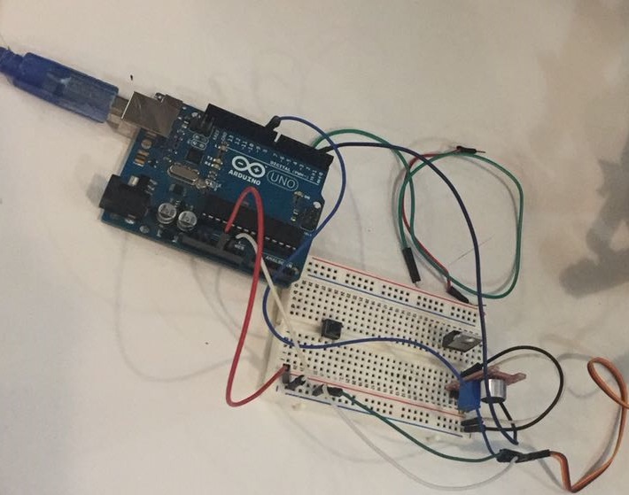
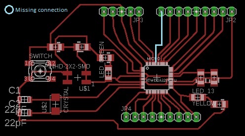
it was hard to make it work but after i get the right code and with the right calibration, it worked and it attivate the sever mottor attach to it. After i made my board, i used a satshakit tutorial. The reason i chose this board is explained in
my final project documentation. So i followed the tutorial to make the board on eagle. The first try i put the wrong microcontroller and it end up not milling correct.
I changed the button as a normal button and not a reset one in case my imput didn't work. I end up forgeting
to put a pin just for the reset pin but i was able to program it doing the reset it manually (touching the pin with the cable).
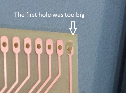
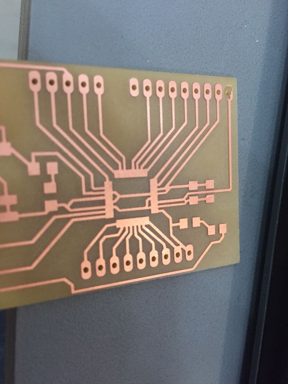
After all ready one the eagle, exported to a png. To make the holes i had to use the photoshop. For the first try i use black background to white hole, it made the holes to big and i had to invert it on fab module.
I used the 1/32 tool to do it. With all the files ready i milled the board again.
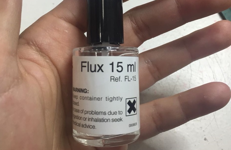
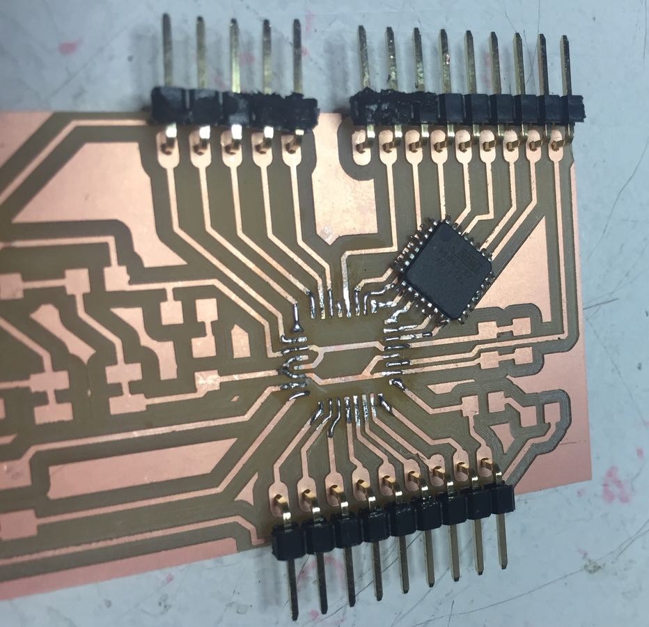
I started soldering the Atmega328p , to do it i used flux to fix better it on the board. To learn hor to use i followed this tutorial:
After i soldered i test the pins and i realise the VCC and the ground were connect but was not the pins. So looking carefull the picture and was a really small connection
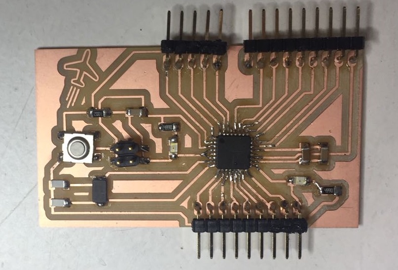
under the microcontroller because of the milling. So i had to unsolder it and break the connection. After i resold it and soldered all the rest. I test again and i had to change a led.
After all, i was finaly able to make my board.
With the board ready i had to bootload it, two of my classmates had the same problem to bootload the board so i just followed this two tutorial to do it with a arduino:
- Nick Gammon
With the help the tutorial i was able to bootload without much problem. After that i connect the FTDI cable to send the code.
I was able to run the same code and make the sensor work!
Here is the file.