An affordable CNC Machine
capable of self replicating
June 24, 2015
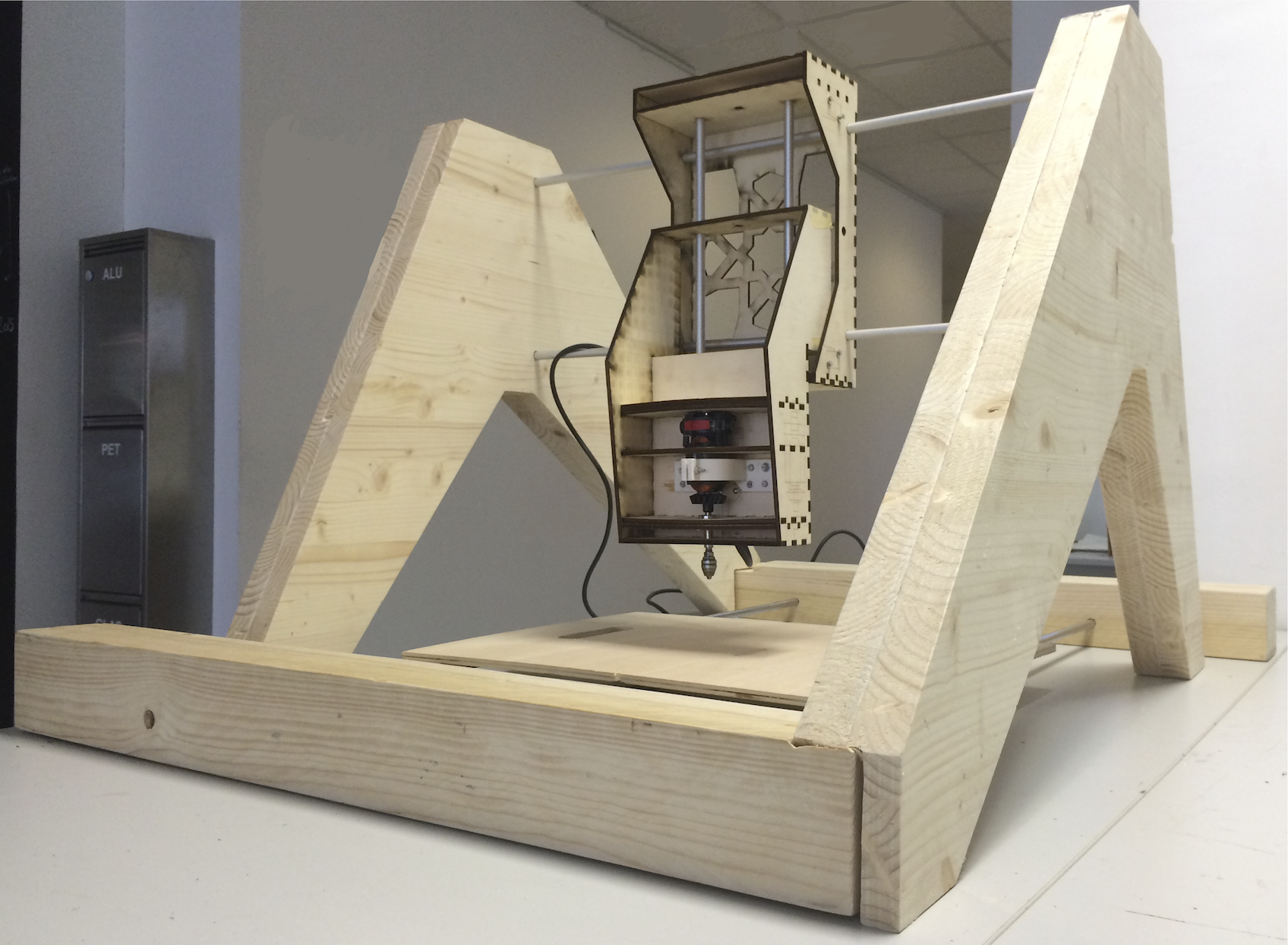
Intrigued by MIT’s Machines that Make project I set out to also develop a low cost machine that could be made using CNC equipment available at the FabLab and that could somewhat be capable of self replicating.
Materials:
Because of its renewable characteristics, affordability and availability I chose wood as the primary initial material with the potential of furthering the design into cast concrete.
Design:
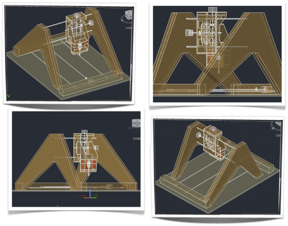
I established the parameters for the design to be minimalist yet structurally stable with the potential of adjustable dimensions. In order to accommodate 3 axis in a stable design, I chose to base the shape on an A-frame. My original idea was a somewhat sliding design to create a scissor movement that would adjust in length and height (possibly as part of its axial movement) with the capability of folding for easy storage and transport.
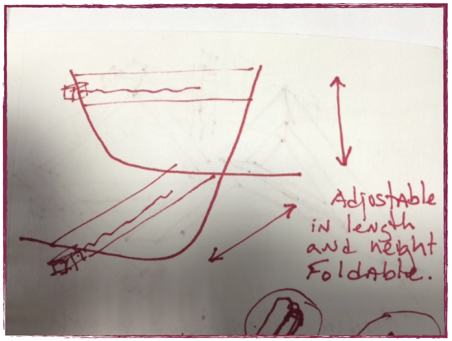
From this initial design concept I developed a Triangular Open A-frame design, while not abandoning the adjustable and foldable idea in its entirety. The machine will be made of two separate Open A-frames which allows for adjusting the size either by using telescopic rods or just by changing rod size on the X-axis and Y-axis. This design feature allows to work on projects of a variety of dimensions. The supporting triangular A-frame would be laser cut in plywood to create a hollow mold used to cast concrete into the triangular A-frame shape providing a weighed stability for the CNC milling.
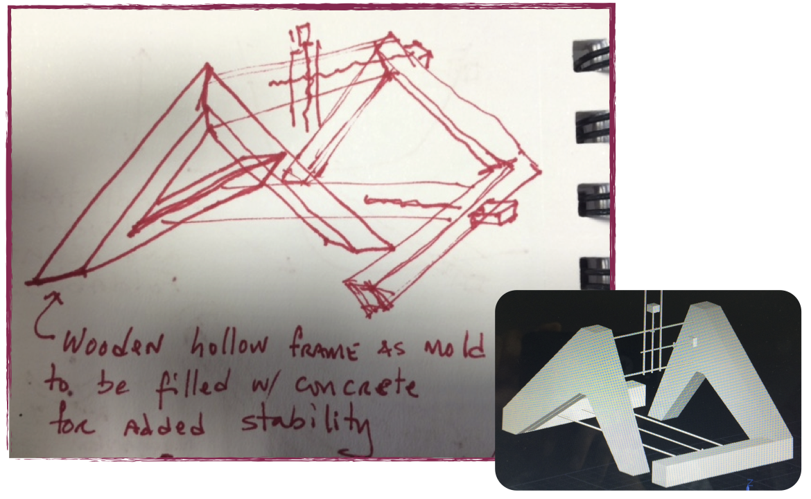
In order to further develop the design before casting I will build a solid wood version as a prototype. For this prototype, the design would no longer be monolithic but assembled from separate wooden pieces. Keeping cost in mind, I decided to make the vertical triangular A-frames out of a double wall 28mm thick plywood and the horizontal legs out of a 80mm squared wood block.
3D Design:
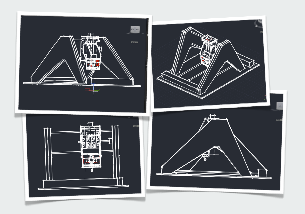
In order to fully visualize the design, I created a detailed 3D model of the CNC machine. The spindle holder is to be built from wood as well with an additional 3D printed clamping support. Hopefully with enough reinforcement to withstand the forces from a rotating spindle.
Mechanics:
The Triangular Open A-frame will be CNC milled. The Y and Z axis stages will be laser cut out of 5mm thick plywood, with 3D printed spindle holder and cable clamps. I will re-use the 2 gestalt nodes and 2 stepper motors provided for the machine building week for the Y and Z axis. For the X axis, I will use a new one-meter threaded rod with its accompanying metal rods and stepper motor as well as building my own gestalt node. Additionally, I will need to design and build my own PCB for the spindle control.
With all the mechanical components planned for, I will first set out to build my machine's Y and Z stages for the spindle holder and the switches at each end of each axis.
Y and Z stages - Spindle Holder :
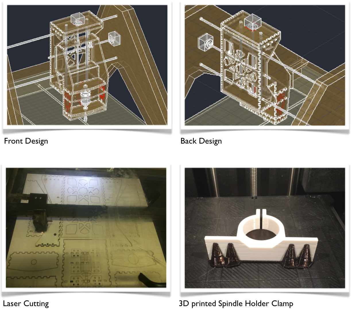
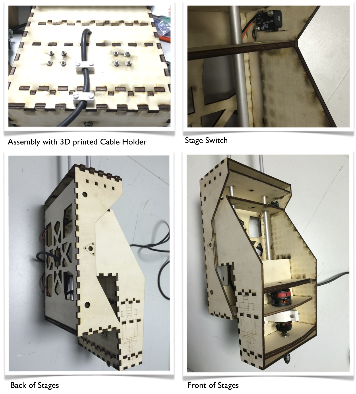
Here is a link to the Y and Z stages Files:
Y and Z Stages Design File to Laser Cut
Spindle Holder to 3D Print
Cable Holder to 3D Print
Spindle:
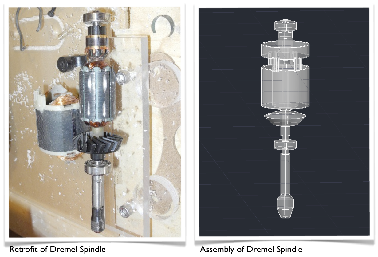
For the spindle that I will be using in my machine, I will retrofit an existing Dremel drill that is no longer functional in its original form. After disassembling and making some adjustments I will encase it in my Z-axis stage. It will be controlled through my Switches and Spindle Control PCB via my Relay PCB.
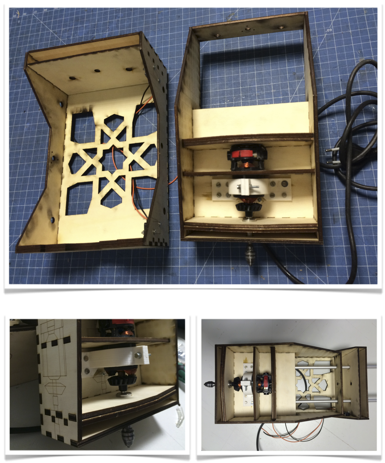
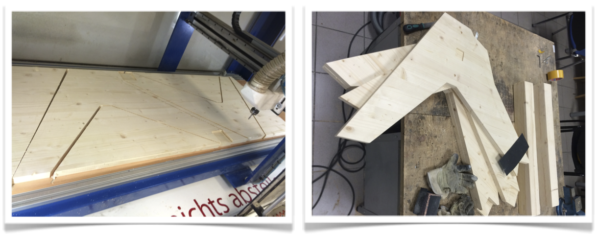
Triangular Open A-frame:
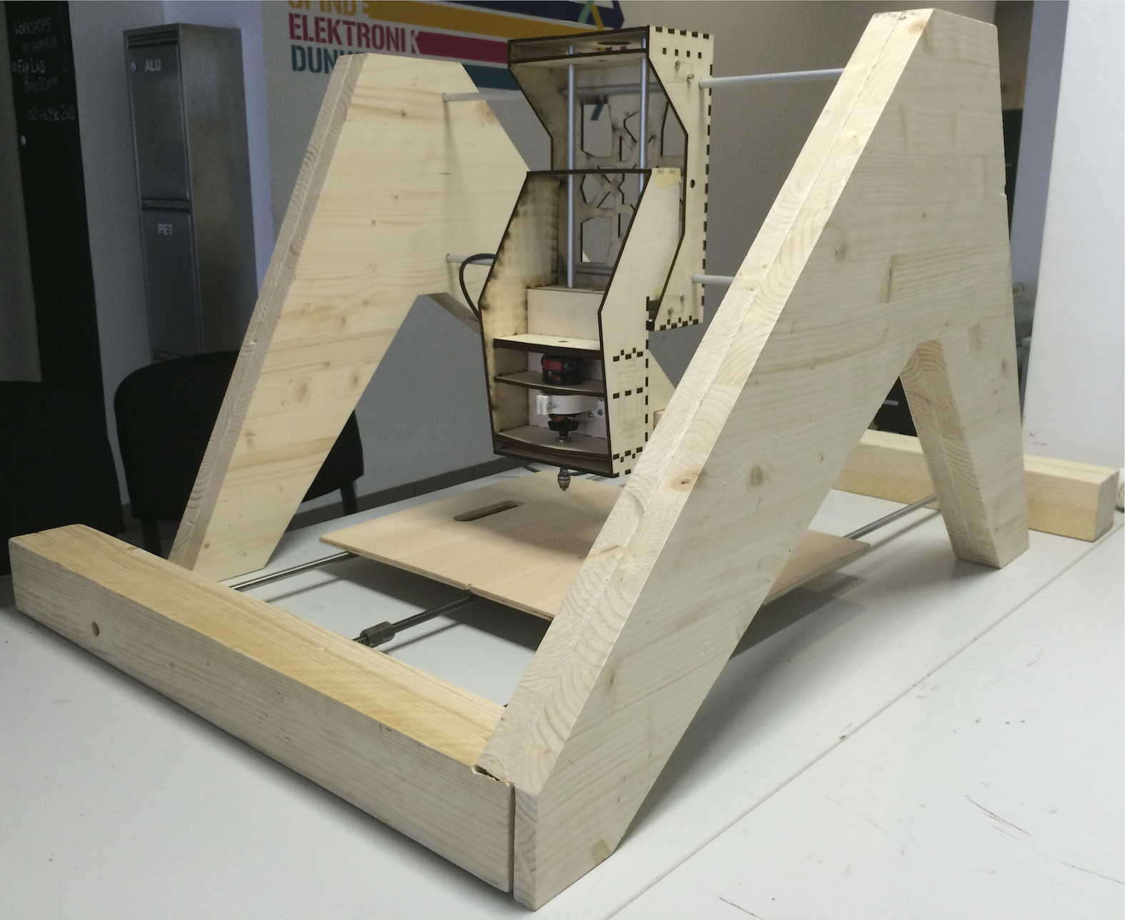
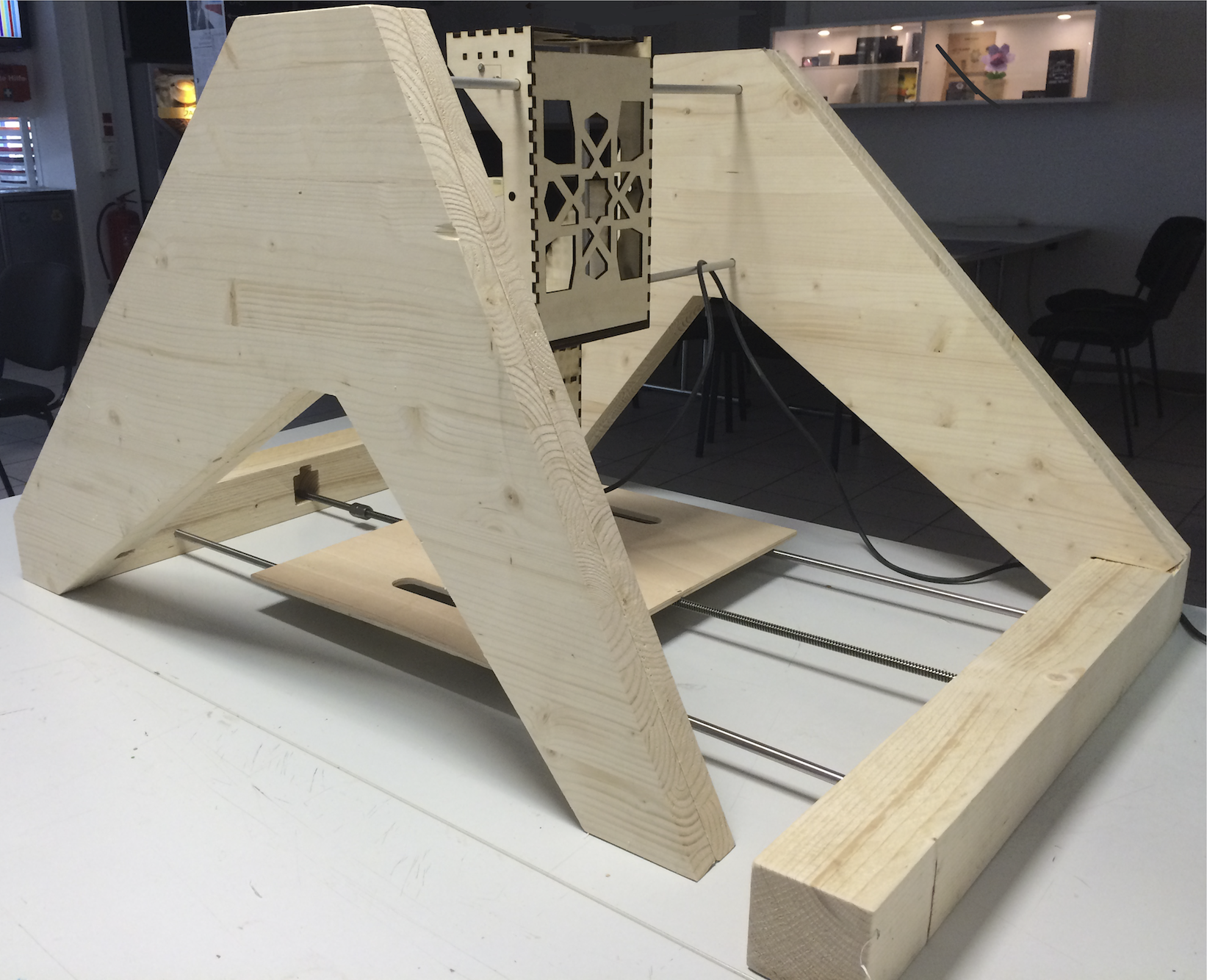
The Triangular Open A-frames will hold in place all three axis. It is made up of three separate pieces which will be bolted and glued together. These pieces were all CNC milled. I had a few hiccups resulting in two broken milling bits, but at the end it was successful except one end which broke off from the main piece when the end mill broke. Thankfully, the milled piece is still functional.
After milling, I sanded all the pieces by hand.
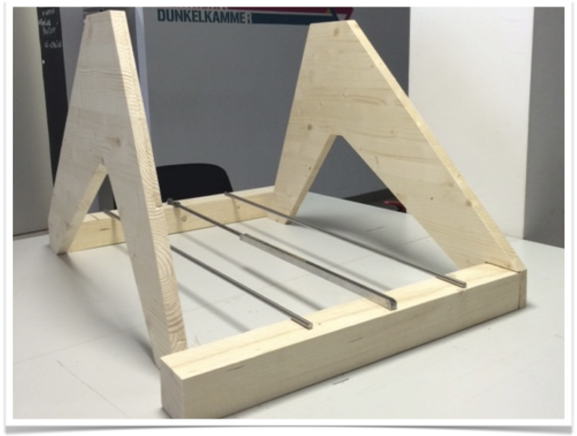
Eager to preview the final product I assembled the two Triangular Open A-frames. I still have to mill the 80mm horizontal wooden blocks so that the second face of the triangular A-frame can lock into place without bolting.
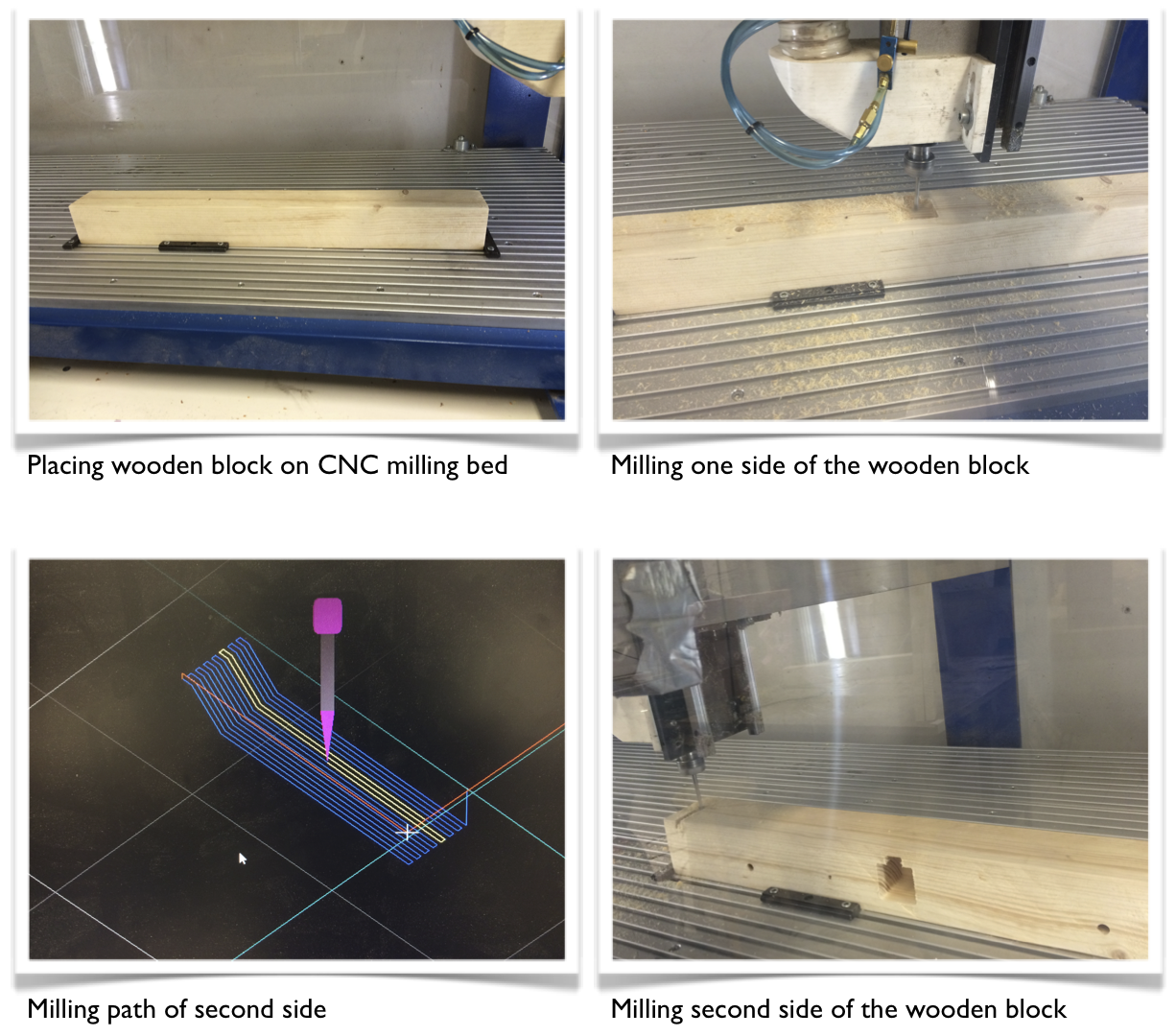
The difficulty of the horizontal wooden blocks which will hold the X-axis is that it is milled in two sides and that they need to be perfectly aligned in relation to each other. I took extra care on perfectly aligning the wooden block onto the CNC mill bed and establishing the 0,0 origin point. This origin point was essential in relating both milled faces of the wooden blocks.
Here are the links to the Triangular Open A-Frames Files:
First Triangular Open A-frame File to Mill
Second Triangular Open A-frame File to Mill
First Wooden Block
First Wooden Block
Top part for both Wooden Blocks
Assembled CNC Mill:

Electronics:
Design and Making of the
Switches and Spindle Control PCB:
In order to control the Spindle and Switches I will use an ATMega 88PB microcontroller. I’ve design an adequate circuit board in Eagle and will mill it.
I decided to use the Fab Modules to generate my G-code. Unfortunately, the .png image I generated from Eagle was a low resolution which resulted in a non functional PCB. I then decided to etch my PCB.
And proceeded to solder all components:
When programming the Switches and Spindle PCB I realized that it was a better design to put the relay on an independent PCB which bridges the wall power source to the machine.
I will modify slightly the design of the FabNet we used during the Machine week, so that the cables come out straight and mill this new design with wider traces for this machine.
For the X axis, I will reproduce Iyan Moyer’s gestalt. Since it’s double sided, I will etch it. Firstly, I will keep on working on programming our existing Gestalt Nodes received for the Machine Week project. Since unfortunately they did not work as they were supposed to I will try to program their micro-controller directly.
As the Gestalt Nodes provided in the Machine week did not work, I will still use their hardware and program directly the micro-controller. This will apply as well to my Gestalt reproduction. My program thus far is able to make the axis move in both directions and to change direction when the switch is reached.
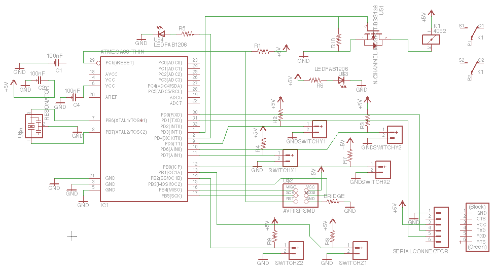
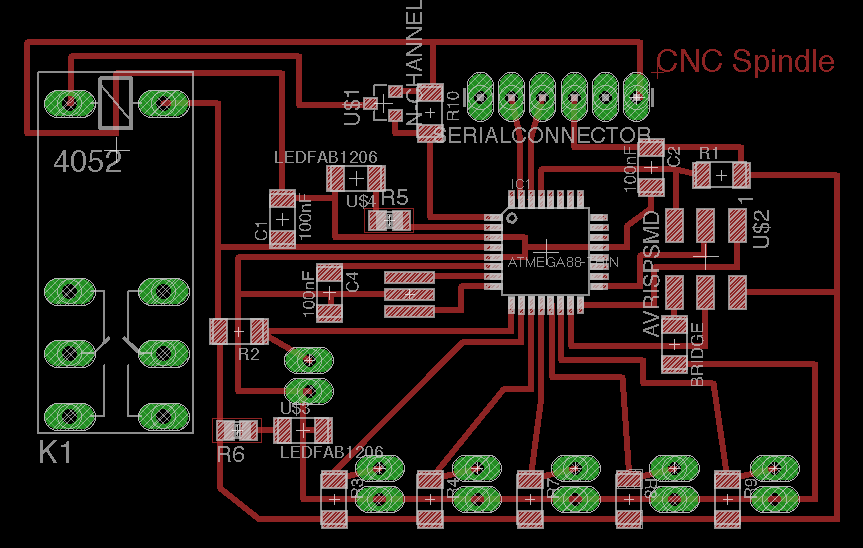
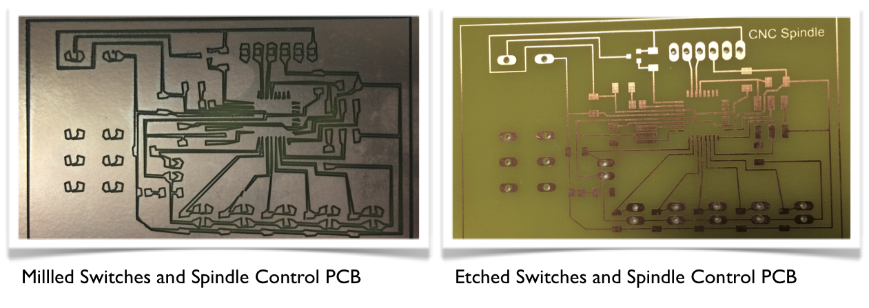
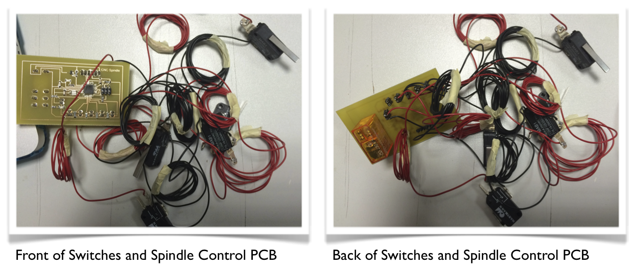
 Here are links to my Switches and Spindle Control PCB Files:
Switches and Spindle Control PCB Schedule
Switches and Spindle Control PCB Board
Switches and Spindle Control PCB Etching Mask
Design and Making of the FabNet PCB:
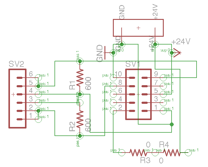
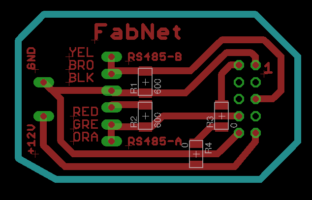

Here are links to my FabNet Files:
FabNet PCB Schedule
FabNet PCB Board
FabNet G-Code
Making of a Gestalt Node for the X axis:

Programming:
Gestalt Nodes:
Here is the link to my Gestalt C-code. A work in progress, as ideally it would be nice to program it such that it could make the different axis move in relation to each other.
Switches and Spindle Control PCB:
This program is able to control the turning on and off of the spindle, react when the end of an axis is reached and to communicate through an interface with the computer.
Programming the Spindle PCB with AVRDUDE and MAC's Terminal:
First verify Device Signature and Check Connections. To make sure AVRDUDE is working, and your AVR Programmer is connected correctly, check first by typing in Mac's Terminal:
avrdude -c usbtiny -p atmega328p
This basic command defines the programmer type you’re using and the AVR it’s talking to. AVRDUDE will attempt to read the Device Signature from your AVR, which is different for each AVR type. Every ATmega328P should have a device signature of 0x1E950F.
Now that it’s verified and that everything is in working order, you can do all sorts of memory reading and writing with AVRDUDE. The main piece of memory you probably want to write is flash – the non-volatile memory where the programs are stored.
Compiling Program:
To compile you choose your .c file and create an .elf file
In Mac's Terminal type:
avr-gcc -Os -mmcu=atmega328p (drag your file location into here: i.e. /users/document/xxx.c) -o (filename).elf
Creating a .hex file:
Converts .hex file into machine readable for a microcontroller: (Changes the created .elf file into a .hex file)
In Mac's Terminal type:
avr-objcopy -j .text -j .data -O ihex (your .elf file).elf (file name).hex
To transfer program into microcontroller:
(transferring the .hex into the microcontroller)
In Mac's Terminal type:
avrdude -c usbtiny -p m328p -P usb -U flash:w:(filename).hex
Please note that:
The Id name of the ATMega328PB
is m328p
Here is the link to the Switches and Spindle Control C-Code Program:
CNC Spindle C-code.
Interface:
The following is the successful interface communication between the Switches and Spindle Control PCB and the computer when the switches are reached at the end of each axis and when the spindle is switched on and off via the computer.
