Networking and Communications
April 29, 2015
Assignment:
Design and build a wired and/or wireless network connecting at least two processors.
This week I will be building a wired network communicating through the serial port between the computer and one or two DC motors to perform different movements: forward, backwards and turn in conjunction to a second DC motor.
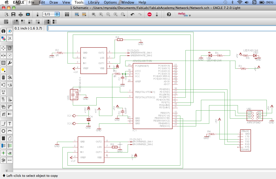
PCB's Schematic Design:
Here are the links to my Networking and Communications PCB Files:
ATMega88PB Microcontroller's Programming Code in C:
Here is the link to my Networking and Communications C-Code File:
To display received information on my computer screen I used the Mac OSx Terminal program to access the serial port by running the little AppleScripting shown below:
New Components used on this PCB:
ATMega88PB Microcontroller:
I will be using this microcontroller because of it is built in Universal Synchronous and Asynchronous serial Receiver and Transmitter (USART) which is a highly flexible serial communication device.
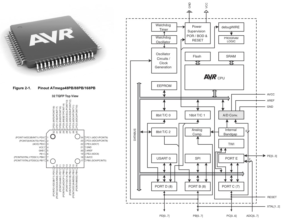 The dashed boxes in the block diagram separate the three main parts of the USART (listed from the top): Clock Generator, Transmitter, and Receiver. Control Registers are shared by all units. The Clock Generation logic consists of synchronization logic for external clock input used by synchronous slave operation, and the baud rate generator. The XCKn (Transfer Clock) pin is only used by synchronous transfer mode. The Transmitter consists of a single write buffer, a serial Shift Register, Parity Generator, and Control logic for handling different serial frame formats. The write buffer allows a continuous transfer of data without any delay between frames. The Receiver is the most complex part of the USART module due to its clock and data recovery units. The recovery units are used for asynchronous data reception. In addition to the recovery units, the Receiver includes a Parity Checker, Control logic, a Shift Register, and a two level receive buffer (UDRn). The Receiver supports the same frame formats as the Transmitter, and can detect Frame Error, Data OverRun, and Parity Errors.
The Clock Generation logic generates the base clock for the Transmitter and Receiver. The USART supports four modes of clock operation: Normal asynchronous, Double Speed asynchronous, Master synchronous and Slave synchronous mode.
The dashed boxes in the block diagram separate the three main parts of the USART (listed from the top): Clock Generator, Transmitter, and Receiver. Control Registers are shared by all units. The Clock Generation logic consists of synchronization logic for external clock input used by synchronous slave operation, and the baud rate generator. The XCKn (Transfer Clock) pin is only used by synchronous transfer mode. The Transmitter consists of a single write buffer, a serial Shift Register, Parity Generator, and Control logic for handling different serial frame formats. The write buffer allows a continuous transfer of data without any delay between frames. The Receiver is the most complex part of the USART module due to its clock and data recovery units. The recovery units are used for asynchronous data reception. In addition to the recovery units, the Receiver includes a Parity Checker, Control logic, a Shift Register, and a two level receive buffer (UDRn). The Receiver supports the same frame formats as the Transmitter, and can detect Frame Error, Data OverRun, and Parity Errors.
The Clock Generation logic generates the base clock for the Transmitter and Receiver. The USART supports four modes of clock operation: Normal asynchronous, Double Speed asynchronous, Master synchronous and Slave synchronous mode.
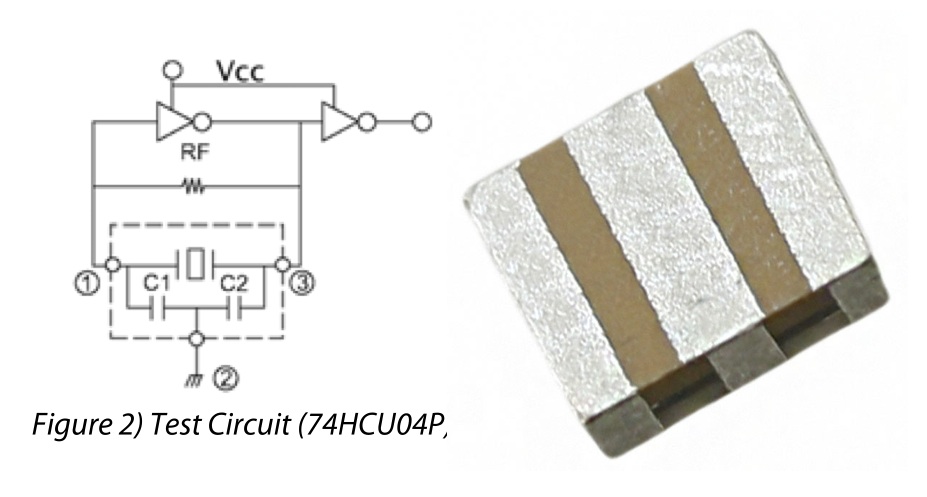
SMD CERAMIC RESONATOR:
The ECS-CR2-B Chip Type SMD ceramic resonator includes built in capacitors for reduced component count. The SMD Ceramic resonator is an excellent low cost frequency control solution when absolute frequency accuracy is not important.
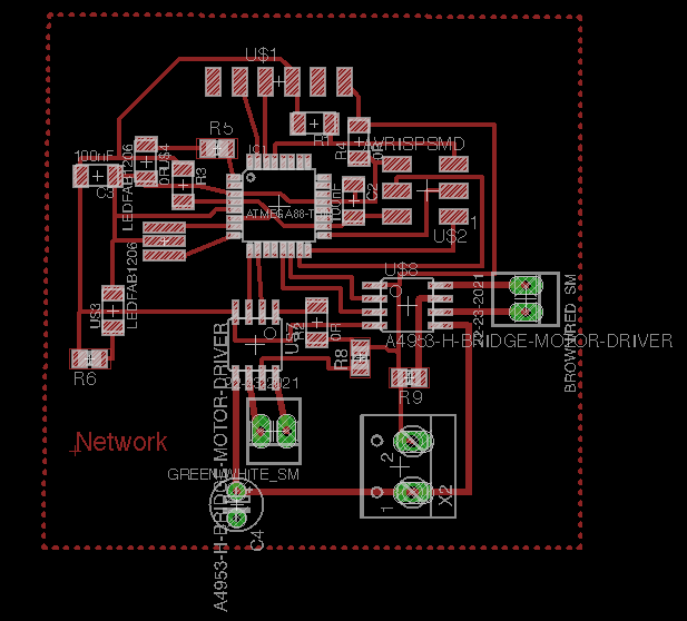
Networking and Communications PCB Design:
 PCB's Layout:
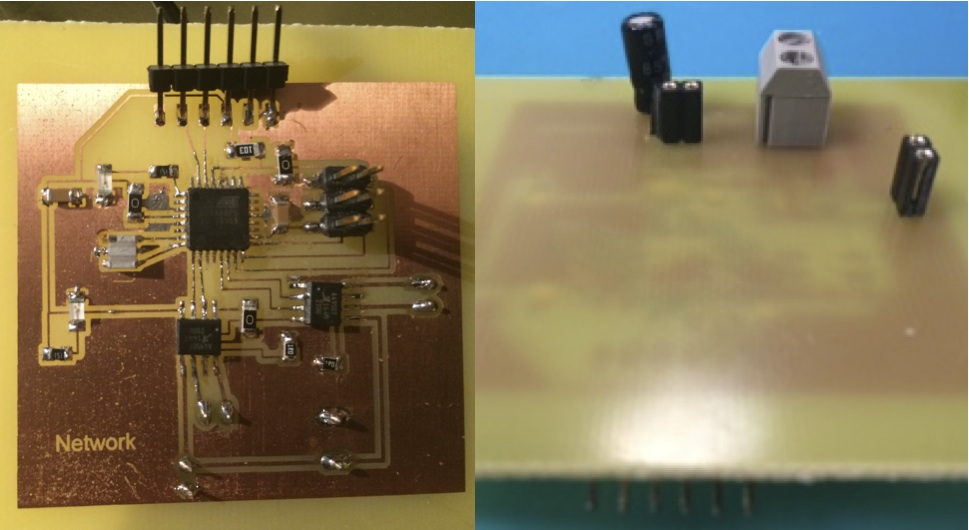
 Front and Back side of PCB with Soldered Components:
Networking and Communications PCB Schedule Design
Networking and Communications PCB Board Design
Networking and Communications PCB Etching Mask
Networking and Communications Programming:
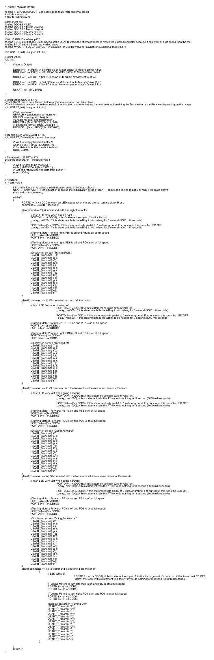
Networking and Communications C-Code
Networking and Communications Interface:
First, launch Script Editor and type/paste in the following code:
tell application "Terminal"
do script with command "screen /dev/tty.KeySerial1"
set number of rows of window 1 to 100
set number of columns of window 1 to 80
set background color of window 1 to "black"
set normal text color of window 1 to "green"
set custom title of window 1 to "SerialOut"
end tell
Compile and save as an application from within Script Editor. As a result, you have a double-clickable application to launch a serial Terminal session. You may want to customize this slightly -- you can change the screen colors or number of columns and/or rows. You may also need to customize the screen command with a different device name if you are using something other than the Keyspan Serial Adapter (do an ls tty* of the /dev/ directory to get the right name).
Screen uses Control-A to take commands directed to it. So type Control-A followed by Control-\ to exit your screen session. If you fail to do this and exit a Terminal session, you'll leave the screen session alive and the serial resource unavailable until you kill the screen session manually.
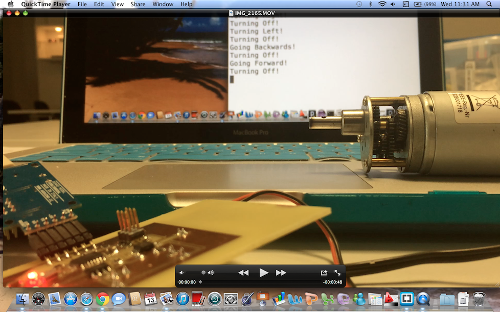
Mac Terminal displaying information received back from the PCB: