
Input Devices
April 8, 2015
Assignment:
Measure something: add a sensor to a microcontroller
board that you've designed and read it.
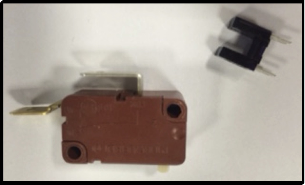
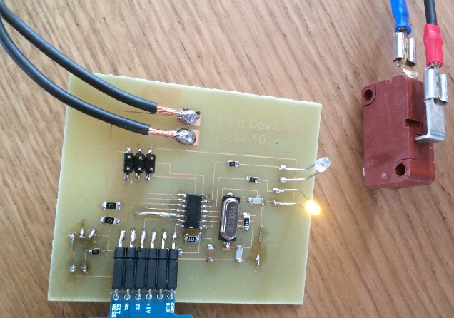
Since I intend to design/build a CNC machine as my final project, I will add two different kinds of switches to my board. One is a standard switch and the other a Photologic Slotted Optical Switch.
Here are the links to my Input Devices PCB Files:
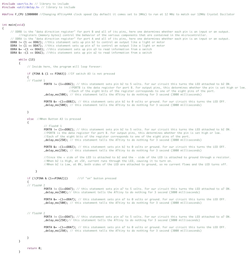
The program for this board will make the LEDs flash alternating at different rates when the switch is pressed (faster) versus when the switch is not pressed (slower).
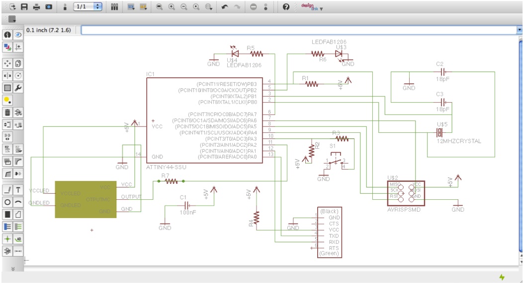
 I modified the design of my previous board, adding these two switches using Eagle. Below are the Schematic Design and the Layout Design of the new board:
 Because of a lack of time to wait for the CNC machine to be available, I etched the PCB board, and drilled the necessary holes to mount the Infrared Optical Switch. I then soldered all necessary components. While programming, I realized that the Infrared Optical Switch required an additional resistor for its LED, so that was added after building the board, hence not in the schematic above.
Input Devices PCB Schedule Design
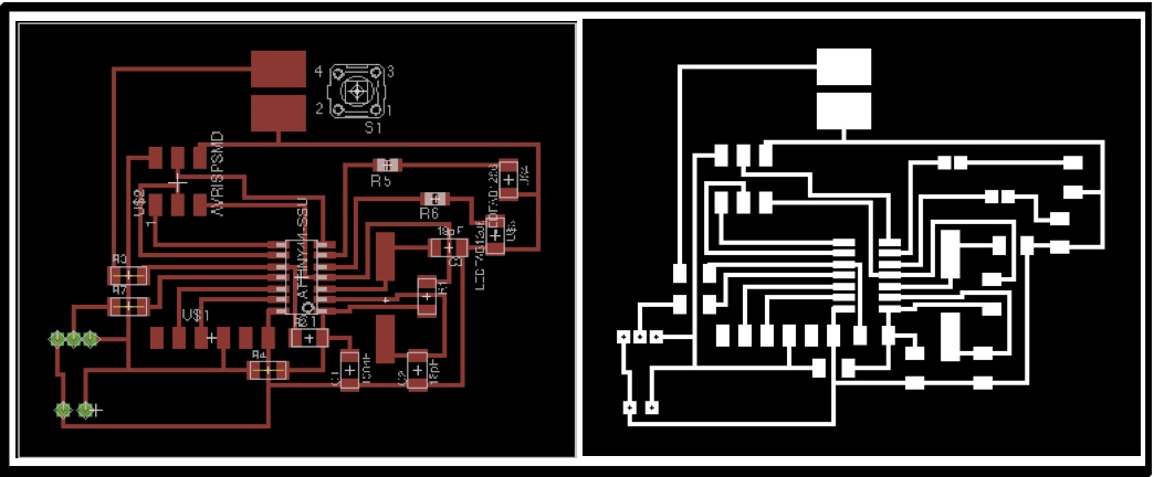
Input Devices PCB Board Design
Input Devices PCB Etching Mask
Programming the micro-controller:
As I am beginning to understand how to program in C, I have tried to keep the coding as simple and understandable as possible. That is why below in green I have written as many explanation comments as possible.
 Here is the link to my Input Devices C-Code File:
Input C-Code
