Networking and Communications Class
13th Worldwide gathering for Fabacademy 2015 feat. prof. Neil Gershenfeld
29 April
6 weeks to Final project
Week's work
After learning and testing input and output devices we arrive to networking and communications, one the last electronic based classes of this years Fab Academy.
So the big challenge for this week is to understand how we can talk between devices via wireless or wired connection, connecting at least two processors.
Professor Niel started this class by explaining what were the advantages of net-working. First of and most obvious is the location factor then the distributed labor, meaning, in a big project instead of having just one processor doing all the required tasks you would have many working in parallel doing one task each. Another good reason for applying this system is its modularity and therefore easier debugging and replacement in case of need without disturbing the rest of the tasks avoiding interference.
A system built by several subsystems that work together sometimes can be a great method for better organizing the architecture of the electronics even if physically they would be placed together.
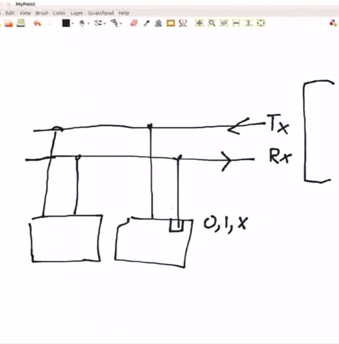
Simplifying, what this means is that all nodes in a network would share Transmit- tx and Receive - rx lines that would be connected to a host that is able to talk and listen. Asynchronously all nodes would receive a signal from the host and while the target node would be active the other nodes would be inactive and so the host thinks he's only talking to one, while, in fact, there are several processors in the net.
Along with rest of the class examples were given about serial communication and how in code the ports should be defined so that all can listen but only the identified one can answer.
After this introduction the basic knowledge requirements where pretty much explained and so What as left to do was decide what boards we wanted to network.
As I am a beginner and beyond the class there is always a lot of research to be done in order to fully grasp all the new concepts, I thought the best choice was to begin with the absolute basics.
For that I followed the always helpful Anna Kaziunas France Tutorials at AS220
Repeating step by step Anna's recipe it was easy to get the expected result.
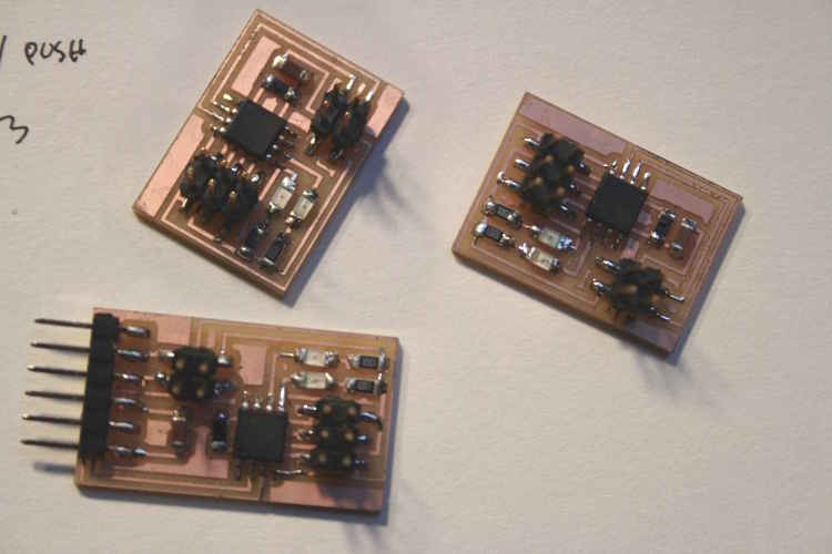
- Get the board designs available in class page links provided by Prof. Niel- mill them (using defaults for mill/cut by fabmodules to the Roland modela)
- Get the code available on Anna's page - an update from Prof. Niels Code
- Flash each board separately using the FabISP
- Every time you flash one you should change the code line where the node ID is defined
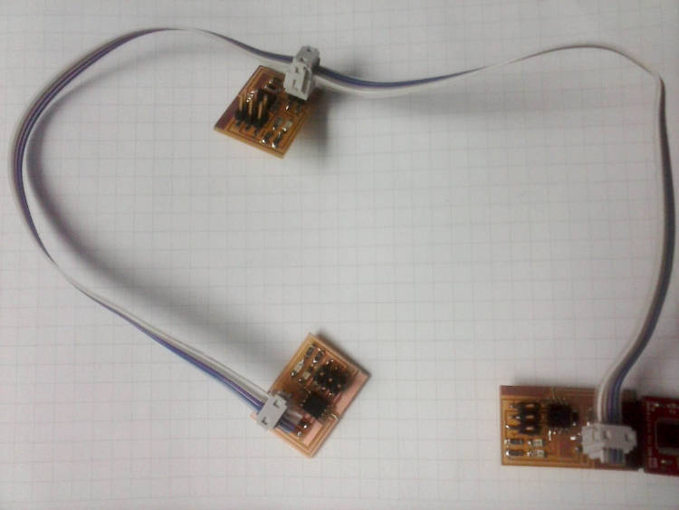
- Build cable with 4 pin connector that will enable the connection of each TX and RX of each board
After following this procedure network is done communication can start via FDTI connector on your Bridge board. If your FabISP is already powered don't flash it with it on it will mess up the rates.
I found this link very useful, please check it - Communication protocols explained [+]
This type of Protocol is then called Inter System Protocol where 2 devices communicate between them through a bus system
The type of inter System Com, in this case is USART that transmits and receives data byte by byte along with clock pulse. That's why it needs to be synchronized and values need to be adjusted.
For visualizing the results of these communications a serial monitor was needed. I used the Arduino IDE one.

// hello.bus.45.c
//
// 9600 baud serial bus hello-world
//
// Neil Gershenfeld
// 11/24/10
// modified by Maria Melo Bento
// Beachlab Fab Academy 2015
//
// (c) Massachusetts Institute of Technology 2010
// Permission granted for experimental and personal use;
// license for commercial sale available from MIT.

#include < avr/io.h>
#include < util/delay.h>
#include < avr/pgmspace.h>
#include < string.h>

#define output(directions,pin) (directions |= pin) // set port direction for output
#define input(directions,pin) (directions &= (~pin)) // set port direction for input
#define set(port,pin) (port |= pin) // set port pin
#define clear(port,pin) (port &= (~pin)) // clear port pin
#define pin_test(pins,pin) (pins & pin) // test for port pin
#define bit_test(byte,bit) (byte & (1 << bit)) // test for bit set
#define bit_delay_time 102 // bit delay for 9600 with overhead
#define bit_delay() _delay_us(bit_delay_time) // RS232 bit delay
#define half_bit_delay() _delay_us(bit_delay_time/2) // RS232 half bit delay
#define led_delay() _delay_ms(200) // LED flash delay

#define led_port PORTB
#define led_direction DDRB
#define led_pin (1 << PB0)

#define serial_port PORTB
#define serial_direction DDRB
#define serial_pins PINB
#define serial_pin_in (1 << PB3)
#define serial_pin_out (1 << PB4)

#define node_id '2'
Another version of inter System communication we did here in the lab was using the values of the hall sensor to write a character in the serial monitor
For that we used Sublime text editor for making changes in the code and GTKterm serial monitor for a visual motorization of the communications.
if (ADC < 450)
{
      put_char(&serial_port, serial_pin_out, '@');
      char_delay();
}
if (ADC > 550)
{
      put_char(&serial_port, serial_pin_out, 'L');
      char_delay();
}
Here is a demo of the magnet aproaching the hall sensor and if bellow 450 it will print a @, if over 550 it will print the letter L.
What have I learned?
- There is still a lot a lot to explore but if the minimum can be reached in a week a lot of research in the world of networking is definitely still to come.