Output Devices Class
10th Worldwide gathering for Fabacademy 2015 feat. prof. Neil Gershenfeld
22 April
8 weeks to Final project
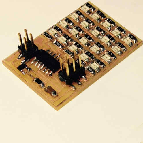
For this week we were to produce/test an output for a board we've designed. But first in an initial phase I thought it was a good idea to start testing one of the boards suggested by Prof. Niel. So I selected his design for the Led Array - Charlieplexing to know more about this technique.
I found several links on the web for Charlieplexing theory explanaition. This instructables one was the most clear to me - Instructables tutorial.
For this first step i used directly Niel's .cad and milled the PCB with predesigned traces. The harder part was to understand Charlieplexing and on what it could be used.
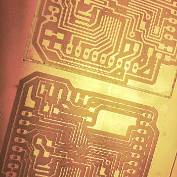
We had the last 1/64 mill broke and I didn't realize it. It was only after milling I understood it was producing hairy cuts. Nevertheless, it milled and Francisco told me for the time being I could save my board just by scratching gently the surface to remove the excess copper dust.
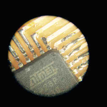
So I did and placed every component despite of the not so clean traces but off course some LEDs were not working when I uploaded the C code provided by Prof.Niel. So I marked them and went one by one in debugging mission.


I reached for our microscope and there were a few soldered areas that were touching and shouldn't be.Thank god for that microscope!
I must say it was a very big relief to make it without having to replace any of the LEDs in the array. I would have been a pain.
Having a fully working LED Array is done so I moved to next board.
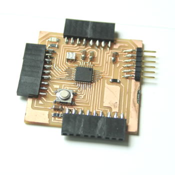
Here I used Alejandro Escarios version of the FabKit and just adjusted in his Eagle file a few traces so that they where more parallel to each other and easy to mill.
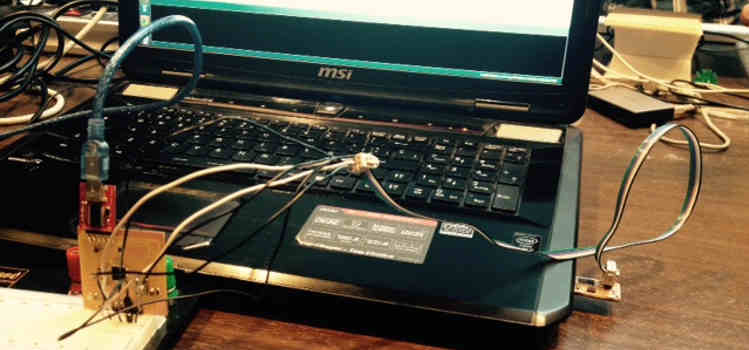
Just like escario I followed the Fabkit tutorial on how to make it and program it namely how to burn the bootloader with that amazingly-complicated-to-do-cable-connector.
Didn't do any holes because I wanted to place male to female pins, so that just like a regular arduino it would be easier to just play around with.
After Burning the bootloader through arduino IDE the programming could begin.
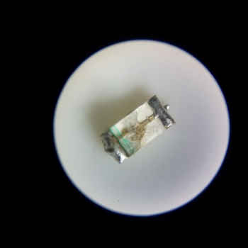
Everything seemed ok but the my led was behaving strangely so check it with the multimeter and the values where a bit of it was when I decided to charge it directly although it was just for a split second that of course it blew. Never do this the exploded plastic almost hit me in the face. Very dangerous.


Keep in mind that to program it via Arduino IDE you should have the pinouts map by your side so that you can replaced the right pin numbers in your code.
I've produced this board because I have in mind using it for my final project. This way I have time to start testing a few ideas before week 18.
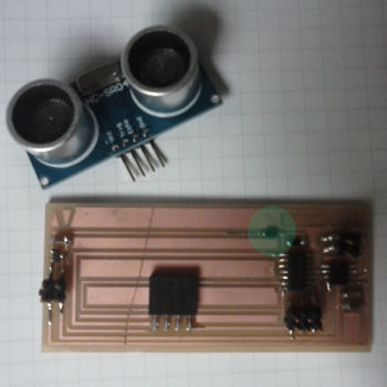
So I grabed a breadboard and did a firts test for the sonar with a LCD display so I could monitor the distances in cm for my Skinetic prototype.
/* HC-SR04 Sensor
   https://www.dealextreme.com/p/hc-sr04-ultrasonic-sensor-distance-measuring-module-133696

   This sketch reads a HC-SR04 ultrasonic rangefinder and returns the
   distance to the closest object in range. To do this, it sends a pulse
   to the sensor to initiate a reading, then listens for a pulse
   to return.  The length of the returning pulse is proportional to
   the distance of the object from the sensor.

   The circuit:
  * VCC connection of the sensor attached to +5V
  * GND connection of the sensor attached to ground
  * TRIG connection of the sensor attached to digital pin 5
  * ECHO connection of the sensor attached to digital pin 3


   Original code for Ping))) example was created by David A. Mellis
   Adapted for sonar-display by Maria Melo Bento

   This example code is in the public domain.
 */
// Use the softwareserial library to create a new "soft" serial port
// for the display. This prevents display corruption when uploading code.
#include <SoftwareSerial.h>

// Attach the serial display's RX line to digital pin 2
SoftwareSerial mySerial(0,1); // pin 2 = TX, pin 3 = RX (unused)

const int trigPin = 5;
const int echoPin = 3;

void setup() {
  // initialize serial communication:
  mySerial.begin(9600);
  delay(500); // wait for display to boot up
  mySerial.write(254); // cursor to beginning of first line
  mySerial.write(128);
  mySerial.write("Maria'S-kinetic!"); // clear display + legends

  mySerial.write("Dist:       cm");
}

char cmstring[10]; // create string arrays

void loop()
{
  // establish variables for duration of the ping,
  // and the distance result centimeters:
  long duration, cm;

  // The sensor is triggered by a HIGH pulse of 10 or more microseconds.
  // Give a short LOW pulse beforehand to ensure a clean HIGH pulse:
  pinMode(trigPin, OUTPUT);
  digitalWrite(trigPin, LOW);
  delayMicroseconds(2);
  digitalWrite(trigPin, HIGH);
  delayMicroseconds(10);
  digitalWrite(trigPin, LOW);

  // Read the signal from the sensor: a HIGH pulse whose
  // duration is the time (in microseconds) from the sending
  // of the ping to the reception of its echo off of an object.
  pinMode(echoPin, INPUT);
  duration = pulseIn(echoPin, HIGH);

  // convert the time into a distance

  cm = microsecondsToCentimeters(duration);

  sprintf(cmstring,"%4d",cm); // create strings from the numbers

  mySerial.write(254); // cursor to 7th position on second line
  mySerial.write(198);

  mySerial.write(cmstring); // write out the TEMP value

//  Serial.print(cm);

// Serial.print("cm");
  Serial.println();

  delay(50);
}


long microsecondsToCentimeters(long microseconds)
{
  // The speed of sound is 340 m/s or 29 microseconds per centimeter.
  // The ping travels out and back, so to find the distance of the
  // object we take half of the distance travelled.
  return microseconds / 29 / 2;
}
Issues and Notes:
- Every time I changed the code I have to disconnect and connect again the FTDI cable otherwise the Display won't refresh
- It was useful to read a few thins about strings - see this Arduino Tutorial links
- Also useful was to start from a known code with the specific libraries for the sonar sensor as well as read a bit on how sonars actually work.
Other OUTPUT Boards Produced:
Stepper motor - unipolar
What have I learned:
- With milling and stuffing everything went ok it was when I powered it that smoke starts coming from the IC regulator.
- Apparently I had done a mistake and placed a 3.5v instead of a 5v one
- After replacing the wrong component I could program it fine
- After that I left it on hold because unipolar wasn't available at the moment and I've learned that I should have done it for a bipolar stepper and not a unipolar one.
- Beginners mistake. Fail and Learn!
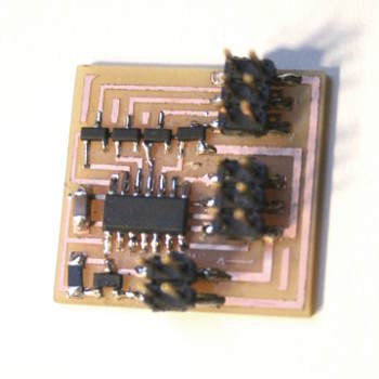
DC motor + sonar
What have I learned:
- IC regulator smoked again. why? Because this time current was flowing both ways of the circuit and I got burned.
- To fix a regulation diode was placed so that th current wold only drive in one direction. Problem fixed.
- Had to learn about H-bridge components and what are they used for.
- After that I could flash it and program it fine so I started testing it just with a DC motor code provided to see if it was working
- Motor was vibrating but just for a few times then I am not sure if it was to much power or not but it stopped working.
- So I went for more information on the differences of each type of motor - DC, Stepper, Servo