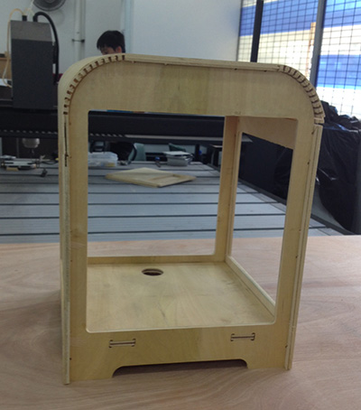
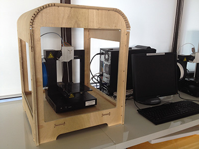
I am planning to build a case/box for the 3D printer. This is because when I print ABS, the draft from the airconditioning and rapid cooling cause the part to warp, especially for large long parts, even though I use a heated platform and use a raft prior to printing.
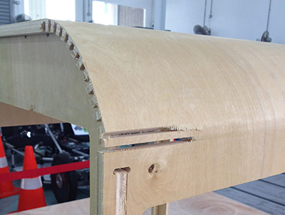
I was inspired to try incorporating flexible joints to give my casing a nice radius. To determine the radius, I decided to test out on a small segment and see if the gap spacing works.
The first try was a failure and at first I thought that the radius of 80mm was too small. But then i noticed that the wood grain orientation was wrong. So I flipped the stock around and did another piece. It worked well on the safe side a radius of 100mm should be fine.
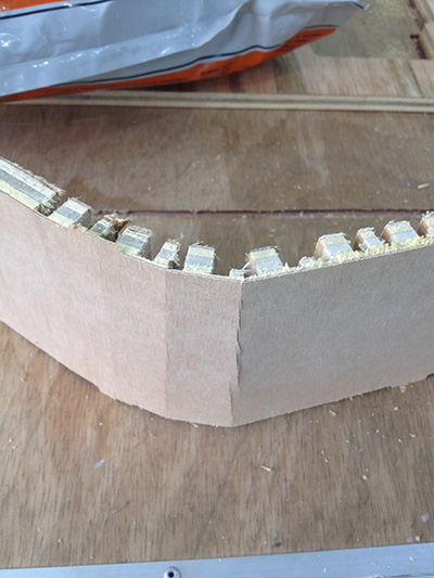

1st Trial - Failure
2nd Trial - Success
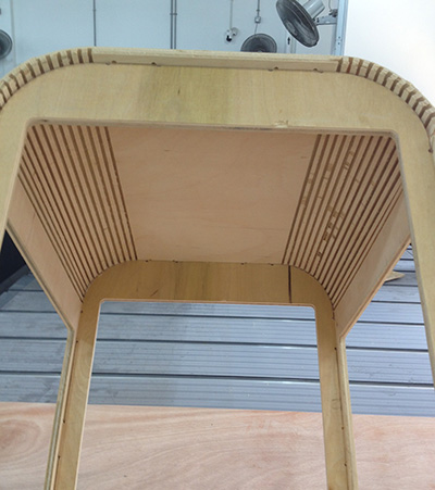
With the radius determined, i finished up my CAD work and ready to convert the files on MasterCAM. It would be nicer if the inner ribs were touching one another, but for that to happen, the slots would have varying values to cater to the bend radius. I am sure it can me worked out...if given the time.
Download the CAD files from
https://www.dropbox.com/sh/zl9fn2p3hdy8t95/AABxoknoXEsAVBy-keQu1ERya?dl=0


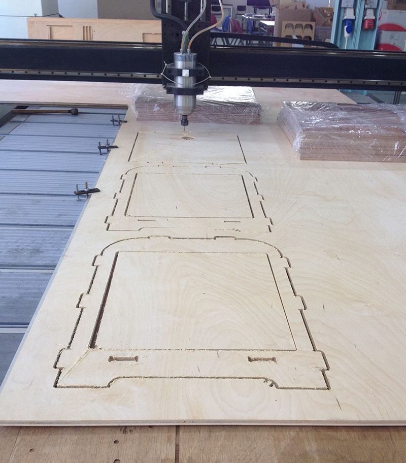
The whole day was spent at the lab. Converting the files to .NC on Master CAM. Having gotten so used to Inventor, I am spoilt and found MasterCAM painful to navigate, need time to get used to it. Setting up the material and ensuring that the warpage is minimised took abit of time too. I did not manage to complete the cutting in a day. Would have to leave it to next week. Looking at the finish, I think a fair bit of post processing is necessary.
Download the NC files from this link
https://www.dropbox.com/sh/dfemnm8i9miep2q/AAD7RHxOnLy5LgXAe0C58a_Aa?dl=0
or
Lessons Learnt
1) Draw on the XY plane and extrude downwards in Inventor so that you minimize flipping the part around in Master CAM - Improves efficiency
2) The poor finish shown below could be improved with the use of downcut sprial cutters that push the splinters downwards, recommend especially when milling wood. The word downcut cutters should not be confused with the definition of Upcut and Downcut Milling, which involves the relation between direction of work piece travel and tool rotation.


3) Use nails to clamp down the centre section of the stock. Clamping at the sides would create a camber as high as 3mm. This would affect your Z dimensions if you are doing 2.5D milling.
4) Whenever in doubt of the NC program, do a dry run without the mill bit and have your hand on the Emergency button.
5) Wear an Apron to prevent grease marks on your jeans :)
6) To get a better idea on router bits, have a look at this document - http://academy.cba.mit.edu/content/tutorials/akf/Downloads/ShopBot%20Trainings/router_bit_basics.pdf
7) These are some of the work that students did this week that I think was cool and an eye opener.
http://fabacademy.org/archives/2015/eu/students/bogers.loes/08computercontrolledmachining.html
8) More awesome sites on CNC furniture