
Electronics Production
Milling
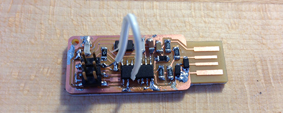
I used Andy's FAB ISP Board this one has incorporated the USB connector in the circuit board.
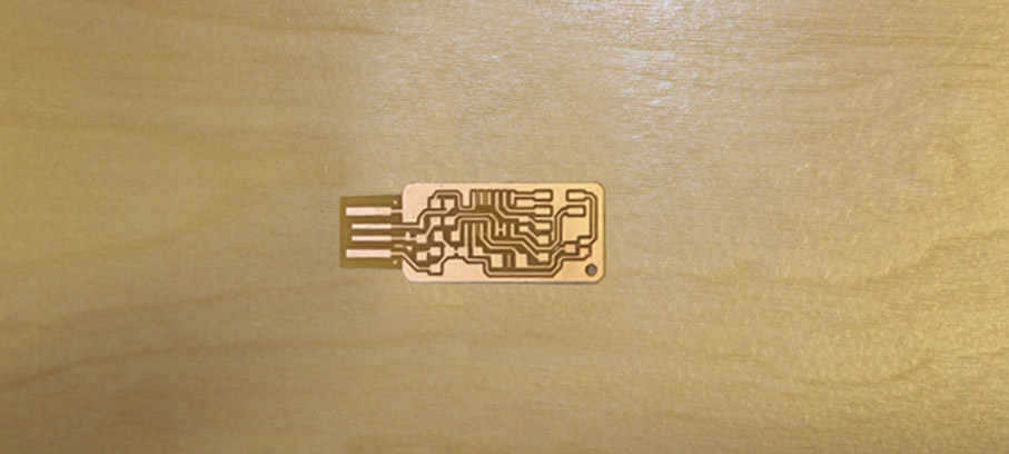
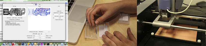
I used the Fab Modules to cut the PCB board with the I Modela CNC, Firstly I connect and set the machine, then I used a bit of 1/64” or 0.04mm to mill the PNG drawing, suddenly when was milling for any reason the bit broke, fortunately at the point was cutting did not damage the board so I could restart the milling changing a new bit.
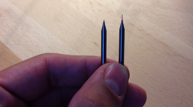
Finally when was milled already I changed the bit for 1/32” or 0.08mm and the cutting drawing with the Fab Modules. The final result was the expected.
Soldering
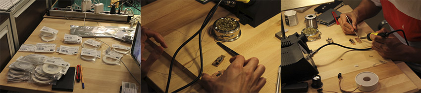
Although I have soldered before was a tough task, soldering these mini components is more complicated than it seems. Firstly I tried with a wasted board, but then I realized was not that easy so I watched soldering youtube tutorials and then was easier. It took me two hours and a half to complete the job, the result is not bad but for the next time is going to be much better.
My results at last components were very good because finally I understood the soldering tricks.
Programing
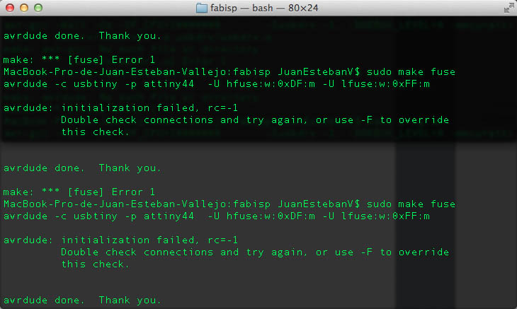
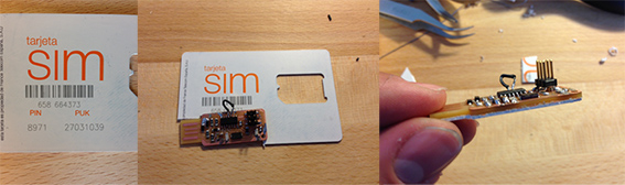
Once I soldered the circuit I proceed to program it, first I download and installed CrossPack-AVR-20130212.dmg from here here. Then I downloaded and unzipped the firmware.zip file Then following the instructions suddenly appeared and error, the Terminal said that there is problems with the connection so I checked again the ports and decided to put a mobile card to make thicker the board.
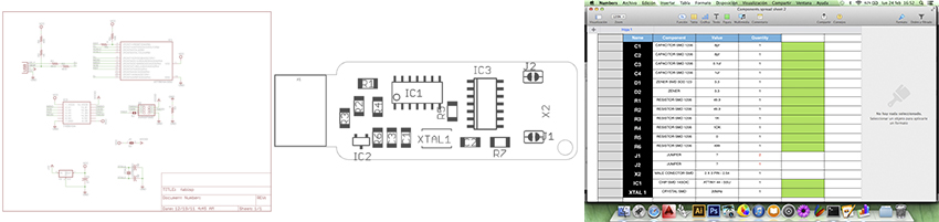
The problem persisted when I tried again, So I checked the components map and I found 2 mistakes. The Crystal and one of the Zenners were put on the opposite way. I had to take them off and put them again properly.
When I was trying to take the Crystal off I broke the legs and two copper filaments, so then more problems again… I was thinking to repeat it again but then I remembered what Neil said about this boards, that the good thing is that you can abuse fixing them.
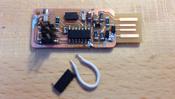
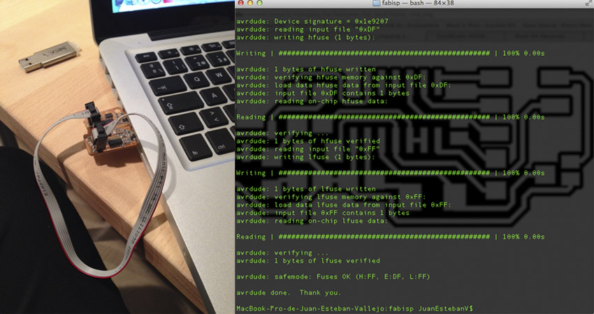
Once I had it fixed I proceed to program it but again same error, so I checked again the contacts and the components map. I connected wrong the legs so then I had to repair it again. When I was doing it the cable collapsed and broke, I realized that was because of I used a very thick one that did not let move flexible so once I manipulated, Broke. I used a more flexible one and solved it.
Then I tried program it again, and was very successful afterwards. Finally I got it, and I feel very happy cause I learnt a lot after so many mistakes. I found the problems and I could solved them. I think this problems are not coming again in the future.
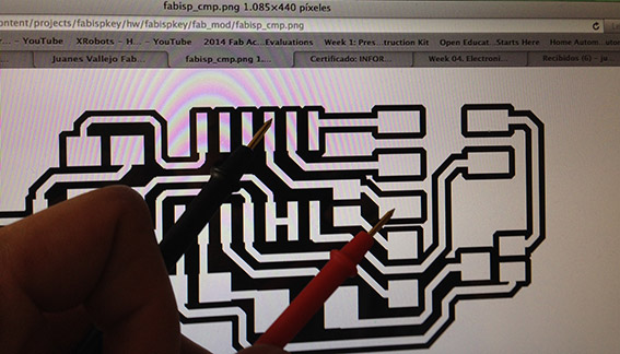
I did not have any knowledge of electronics before, but I think now I know the tricks or at least the steps to start making a circuit. It is very important to check the components map and follow a logic to soldered them, because otherwise you will have problems putting others that are very close.
Finally I am ready to program it, so follow the next steps:
-Plug the FabISP to your USB port
-Open the Terminal and type
-cd ( + file folder ubication)
-make clean
-make hex.
-make fuse
-make program
And it is program!
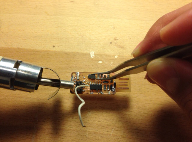
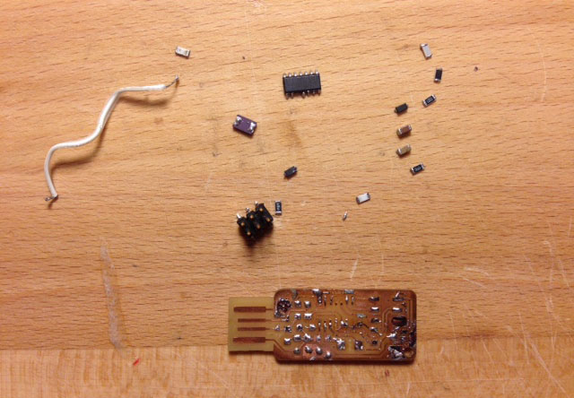
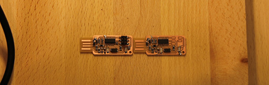
After using few times the fixed FabISP the cable I put broke; So I decided to make a new one. Was a very good experience because I felt I have Learnt, I made it so quick and with good soldering skils.
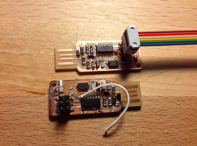
Also we have a new heat gun so I practiced unsoldering the components of the old FabISP and save some components. Attiny44 is broken so I threw it away.