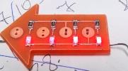

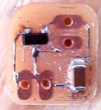
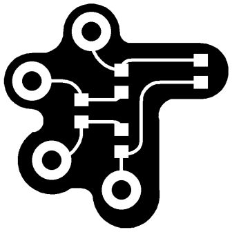
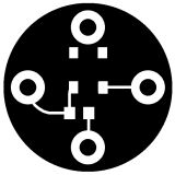
This is the second design of LED BOARD
Press "Скачать" to download the Eagle schematic
The
Press "Скачать" for the downloading
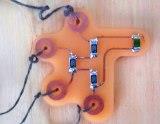
The Leds are switched on with the button.
Who's done what beforehand?
The adafruit made the lilypad arduino. This is the inspiration of the project.
What did you design?
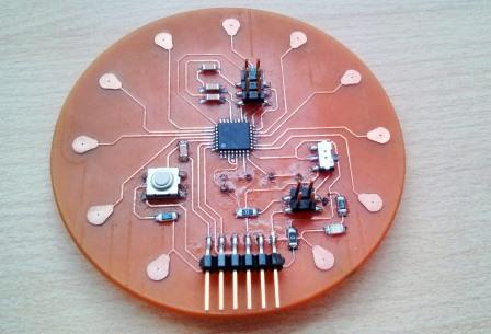
I designed the arduino Medusa,
with the help of an adviser and electronics engineer Jose De los Rios.
The rest of the boards I modified using  the fab academy´s schematics as a reference.
What materials and components were used?

I´ve mentioned them already in THIS ASSIGNMENT XVII.
Where did they come from?
All the materials I had from the FablabTecsup.
How much did they cost?
 During the project development some boards I milled did not function.
The Modela is good for milling small boards.
Some vias of my arduino elevated and some pins of microcontroller were removed.
The second one was milled  more or less satisfactory
but did not function because I made a mistake.
 I used the crystal 20OM instead of 16OM.
So the third one I milled with Gravograph and the result was excellent.
What parts and systems were made?
I made an Arduino, one button board and one temperature sensor board.
What processes were used?
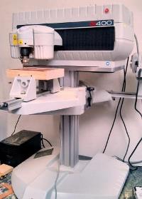
For the Arduino fabrication I used the Gravograph machine
because only this one could make precise milling of thin vias and pins.
What questions were answered?
Till the last moment I did not know how difficult it would be to make this project.
The conclusions are:
It`s not difficult.
To make this project you`ve got to know the following software and techniques:
Electronics basics
Eagle
Roland Modela`s software
How to mill in Roland Modela
How to solder
How to program your boards
How was it evaluated?
 I programmed the Arduino and programmed the button to switch on and switch off the leds.
I evaluate this project and a completed well done project.
I had clear understanding of what I had to do and the clear understanding of what I have done.
I learned to make electronic boards and arduinos and to program them.
I have already known the CAD designing and molding and casting.
I also have experience of doing the composites.
Well, as you see I`ve chosen the most difficult task for me to make.
What are the implications?
The conclusion is that this project is easy to make.
You`ve got to learn some techniques to do it.
And then you`ll be able to make wearable electronics for your clothes.
So, I want to say that I am convinced that everybody can do that.
Imagine, that everyone makes electronic accessories in their house. That`s great.
ELECTRONIC BOARDS
|
Its the first version of the LEDS board design |
| |
This is the second design of LED BOARD Press "Скачать" to download the Eagle schematic |
|
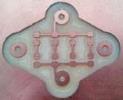
The voltage REGULATOR |
| |
The |
|
Press "Скачать" for the downloading |
|
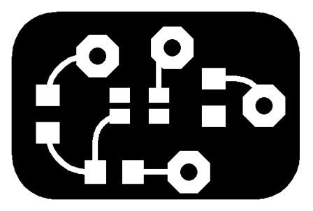
This is the BUTTON BOARD |
|
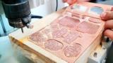
The cutting process |
WATCH THE VIDEO GRAVOGRAPH functioning!
|
The arduino I´ve made with the help of Gravograph machine due to the fact that the routes are very thin and requare a thin drill of 3 mm with the point of o 0.15 mm. |
// #include <avr/io.h> #define output(directions,pin) (directions |= pin) // set port direction for output #define serial_port PORTC float eps = 0.5; void setup(){ |
The code for temperature sensor |
//Include Files |
The CODE for MEDUSA LEDS |
const int buttonPin = 2; int buttonState = 0; void setup() { void loop(){ // check if the pushbutton is pressed. |
The Button`s code |
float centi() int dato; //Esta fórmula sale de la relación del sensor con los grados. Ésta es fácilmente rastreable por la web pero vamos a intentar explicarla un poco: El sensor de temperatura LM35 responde a variaciones de 10 mV por cada grado centígrado. Si el sensor detecta 1 grado centígrado a la salida del sensor obtendríamos 10 mV. Ejemplo: 26,4ºC = 264 mV = 0.264 V. void setup(){ if (Centigrados >= 37.01 && Centigrados <= 38.00){ |
The code for programming the Arduino
|