The goal for this week assignment is to model a possible final project, for this reason I chose to work on one of its main components, the peristaltic pump. Because I have a not so much experience on CAD software I started with a hand drawn sketch to get a general idea of the main aspect of the pump and then to estimate approximate proportions for the mechanism. For this task i will make use of Autodesk Inventor and Rhinoceros 5 and then compare the pros and cons of each.
You can download the blueprints and CAD files here
Software package used for this assignment
Autodesk Inventor
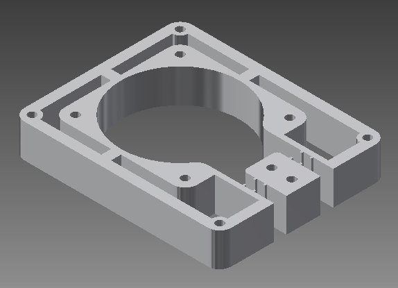
I have previously worked with SolidWorks modelling simple parts, so working with inventor was not too complicated. For designing the pump I found it important to first complete the core piece, where the upper and lower lids are attached, as this will contain the bearings that will allow the flow of liquids from the containers to the mixing terminal. I considered round edges in the internal part of the core because the friction between the bearings and the inner walls would wear the tubings.
Core Piece
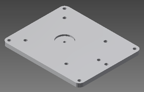
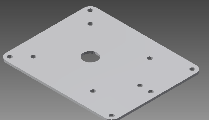
Later I designed the upper and lower lids, considering holes so they can be fastened with bolts and nuts. The last part for design was the central piece wich holds the bearings and inclues a transmision system for an enconder that will be used to sense speed and direction of the liquids in the pump. I also considered a small gap between the bearings and the inner walls of the core for allowing the flow of liquids.
Lids
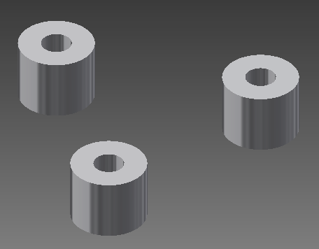
Bearings
Central Piece
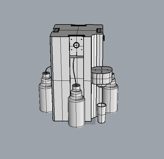
Finally I made an assembly file to make sure all the parts fit ant to test the rotation of the central part. Then I modified the materials of each piece and the colors so it can be better appreciated.
The software used to screen recording is Cam Studio is Open Source and outputs AVI format video files. The link to the website here
Rhinoceros 5
Up to this moment i had no previous experience with Rhinoceros or any other Nurbs design tool. However this software is more flexible and intuitive to work with because of the free form drawing. During the process I had some problems with the trim and project geometries tools, however the biggest problem I had was to make pieces that needed multiple extrusions. While modelling the central piece I had to change the plane coordinates several times and perform Boolean unions for each extrusion to make solid objects. Probably the design process would have been easier with prior experience in the use of this program, but because i already had a clear concept on the design I only had to adapt to the current tools and how to use them.
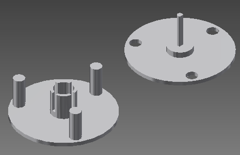
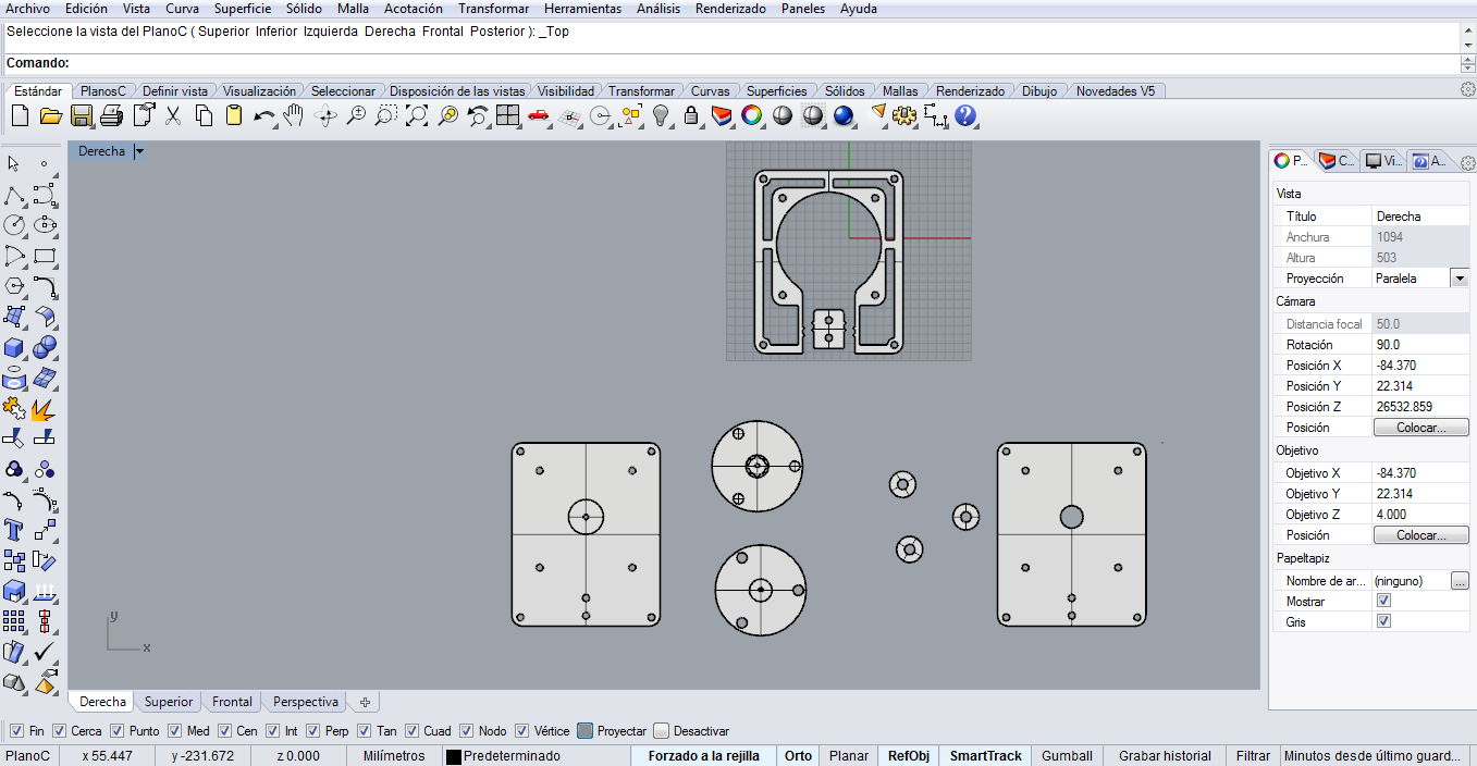
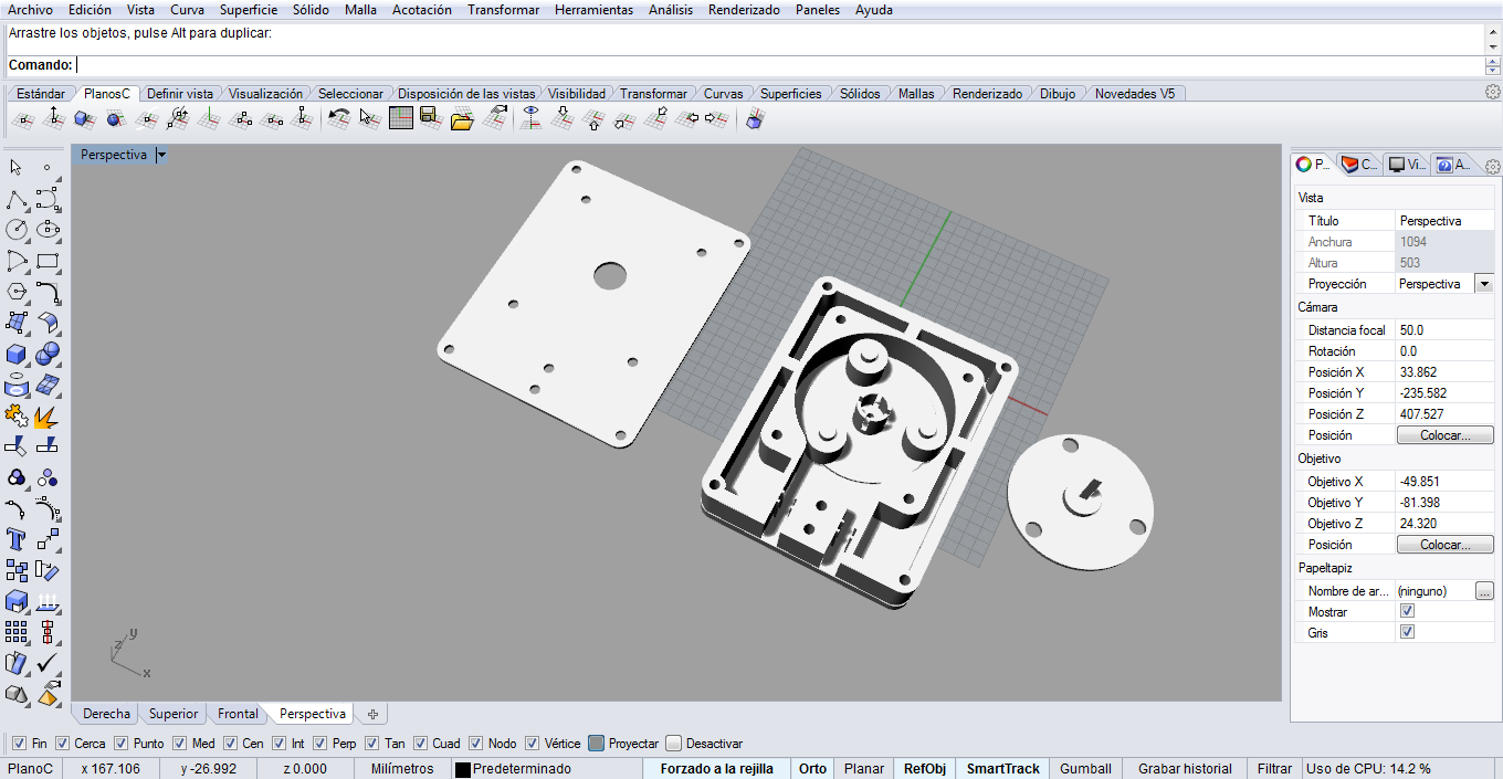
Diferent views of the same object designed in Rhino
-Assembly file gives you a main idea on the final aspect of the object and how the moving parts works
-Constrains for assembly
-GUI is user friendly
Rhino Pros
-Intuitive
-Free forms
-Easy to close loops
-Easy to generate patterns
-The pluggins are interesting specially grasshopper though i have not used it for this assignment
Inventor Cons
-Constrains for 2D sketching
-Patterns add constrains that are hard to deal with
-Many functions like close loops are not too obvious
Rhino Cons
-Too many tools and UI overloaded
-It's not parametric unless you use Grasshopper Plugin
-Tedious to use with work planes (C plane to surface)
I would like to make clear that this chart comparison it's based on my own experience with both softwares, if something is wrong about characteristics in particular it's because I have not tried all the tools.