Electronics Design
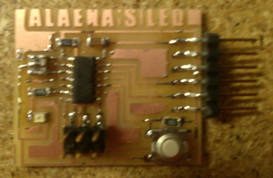 This week's assignment was to modify the Hello Echo board by adding an LED and a button.
I did this by using the free software called Eagle, which allows the user to create a schematic and board layout that is ready to be milled. I used the given tutorials to learn the basics of Eagle. I had to download specific libraries for the Hello Echo board. Luckily, I did not encounter any issues while installing the libraries and making them available for use.
Starting with the example file in the Hello Echo project, I peiced together the schematic with the suggested componants.
I ran an error check, and corrected a few things that were not actually connected, and a few that I forgot to label.
The end result of the schematic looks like this:
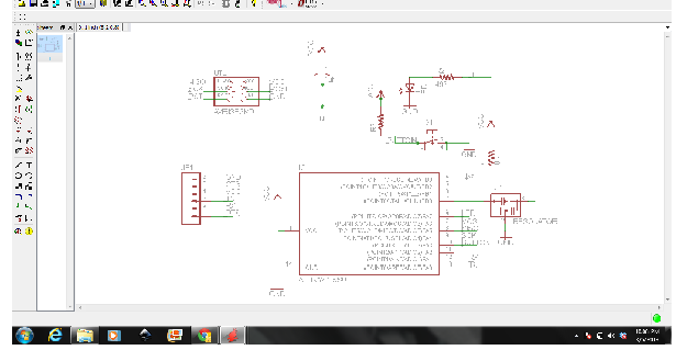
I felt confident that all of my componants were correctly connected, so I moved over to the board so that I could draw the traces.
It took me a while to do this. It was hard to get everything in the right place, and I had to redraw several times. After I thought everything looked great, I turned off the componant layers and did an error check. There were no errors that were important, so I was ready to export the file. The board file (with all layers turned on) looked like this:
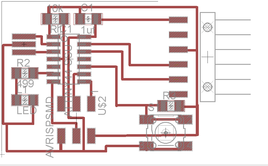
I used GIMP to export and edit the files so that they would be ready for milling. I inverted the image so that the background would be black. Then, I edited the size of the image and saved it into two files, one as the outline for cutting and the other as the actual board. I added my name onto the board for fun:
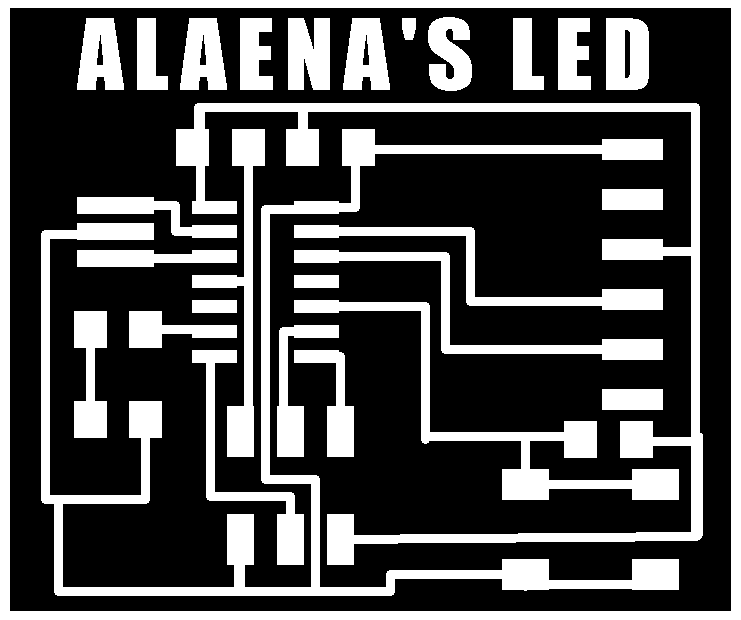

Time to send to the milling machine! I already knew how to set up the Modela and cut out the board from the last assignment. Here it is in action:
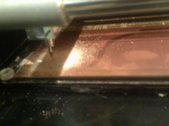
That finished quickly enough...
I stuffed the boards following the above schematic. I really had no trouble. Even though my microcontroller was on a little crooked, everything still seems to work perfectly when double checked with a multi-meter.
Here is the completed, stuffed board:


