input devices
Week 10 Overview
The input devices week covered how to use sensors to read values such as temperature, light or sound. The aim of this week is to experiment with the sensors. In the future interface and application programming week 12 we'll be looking at how to make visualisations of the data readings from the sensors on the computer screen. In the output devices week 13 we'll probably get the sensor data coming in to be sent to output devices.
- Link to this weeks academy information page - input devices
- There are so many input boards I could make. Here's a list of all of them which might be useful in the future
- Link to the tutorial - Input Device Examples - in C
Assignment
Fabricate one of the hello world input boards and programme the board. Neil gave us examples to work from. There are all on the input devices fab academy page - Link to this weeks academy information page - input devices
Description of Input Devices Work
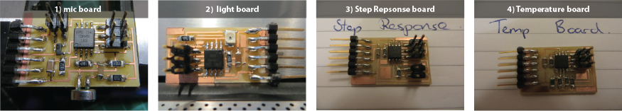
I choose to play around with 4 Boards. The mic, step response, temperature and light sensor boards to start off with.
Step 1:
Fabricating the Boards
I fabricated 4 boards using the same process I went through in the 'electronics production' week.
- Link to temperature board traces
- Link to layout of where the temperature boards components should be placed
- Link to mic board traces
- Link to layout of where the mic boards components should be placed
- Link to step response board traces
- Link to layout of where the step response boards components should be placed
- Link to light board traces
- Link to layout of where the light boards components should be placed
Step 2:
Programming the boards using the FabISP, C and python.
I spent a bit too much time on making the boards so I only programmed the temperature
board and the step response board. I've also programmed the light board in arudino to use for the
'Interface and applications' week.
Temperature Board
- Link to the code.
- Link to the Makefile. download and send to the ATTiny45 using the FabISP.
- Link to the Python file, which reads from the temperature sensor on the board.
Step Response Board - the loading example.
- Link to the code.
- Link to the Makefile. download and send to the ATTiny45 using the FabISP.
- Link to the Python file, which measures what's called the step response. It can be used as a touch sensor. I'll explain more about this later below.
Step 3:
The boards working
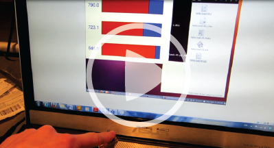
Here's a video of temperature sensor Working.
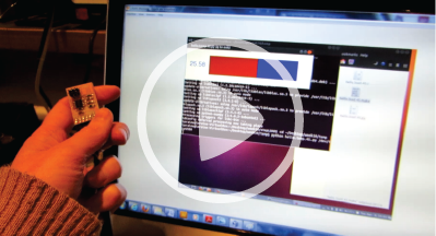
The temperature really spikes when I hold it as the side of the laptop where the fan is pumping
out heat from the laptop.
Here's a video of Step Response Board Working.
I was playing around with different materials to see if it would measure anything across these
Step 4:
Understanding what the sensors and the programs are doing
Temperature Board
A thermistor is a kind of resistor that depends on temperature. It varies the resistance
when effected by temperature changes. This results in differences in voltage sent back
to the Attiny45 chip.
Following the lecture,
I've written a more detailed description explaining what happens with the temperature board
here.
Step Response Board
We've used resistors to act as proximity sensors on this board.
Following the lecture I created a detailed description explaining what this board is doing
here.
Notes from INPUTS week
- pin can put voltages out or it can read input
- you can switch on a pull up resistors and then
- there's a multiplexor that can send pins to different destinations
- go to registers to set the pins. there's a port register to write this out. direction register used to tell it if it's an input or output. The pin register is used to read the state of the pin. There's 3 registered used to talk to the pin
- comparator - - compares two voltages on two different pins
- multiplexor - pick any pin and send it to the comparator
- A/D - analog to digital conversion - useful link for understanding analog and digital signals - https://learn.sparkfun.com/tutorials/analog-vs-digital
- clock - A/D has a separate clock for more accurate answers
- RC clock is important for this week because most of the examples use the RC clock . The RC clock needs to be calibrated properly. If it isn't you won't get data from it.
Week 10, Mar 27