Classes > electronics design
STEP 1: DESIGNING
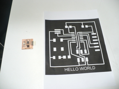
To do the task of this week I had to check the designs sent by the cba.academy website and it is showed.
 |
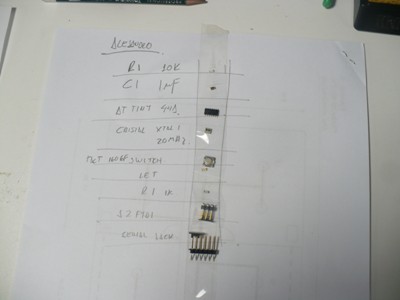
Also there are several variants about he same task that I could check in the last classes. The elements to take in account for design the board are: 1. FTDI-arduino downloaded from SparkFun library (1) 2. Attiny 44 (1) 3. Resonator (Xtal, 20 Mhz)(1) 4. Header (1) 5. 2 resistors (1K, 10K) 5. Capacitor 1uF; and 6. Led (1) 6. Sswitch downloaded from fab librarry |
 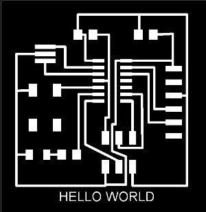 |
After several attempts to achieve the best design I had some problems in determining each connection route because there were many crosses to solve as showed |
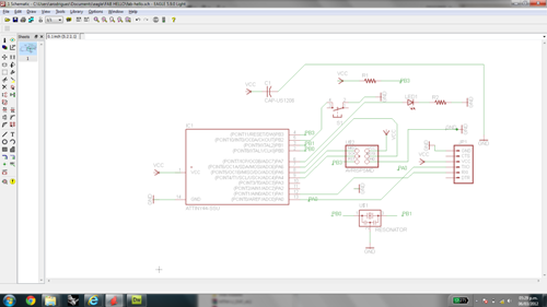
For completing the board I had to adding a led in serial with a 1K resistor and one swuitch using the Eagle program where it was a whole challenge to locate among the other elements these new elements. Fortunately this program allowed us find in the schematic enviroment the correct conections between the elements to assemble hence to draw the final routes designed to be milled. I must mention that we needed an aditional library Spark Fun to get the FTDI component because the fab libraries had not it. This can see in:
https://github.com/sparkfun/SparkFun-Eagle-Library
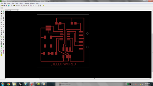
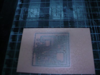
I used also the Paint program to edit the size and do the corresponding borderline of the board for cutting and separate it after milling.

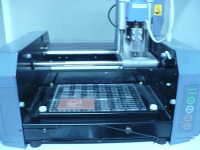
STEP 2: MILLING
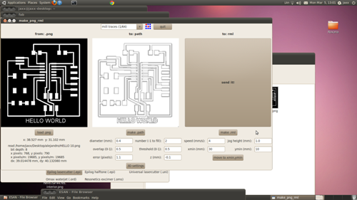
Once the design was completely defined it is necesary to save it as .png and can open by the program for the Modella milling machine where it was necesary to set some machining paramters as diameter, speed and position acording with the location of the plate over the machine work table.

Here I did not want to commit the same failure as I committed with my ISP board task when the board rose while it was being milling (see electonics production )
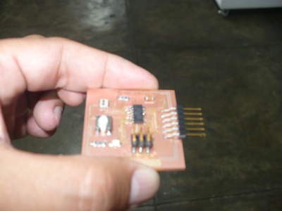
STEP 3: ASSEMBLING
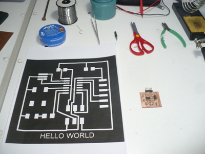
Finally, I have to assemble all the components but at first I have to select each element and locate them over a piece of paper taking care no lose them as some of them are very small size
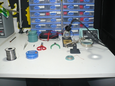
As it is showed we must to having all the element for soldering at hand (the soldering kit)
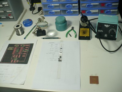
Here, I am making the assemble of my board by soldering process but taking care that each terminal corresponds with its correct position.
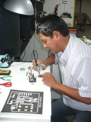
Finishing the assembling I hope all the soldering points are well made. Honestly I had some problems specially with the micro controller for being too small then I had to redo the soldering.
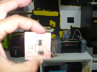
Particulary I am very glad to have made this task where I am improving my skills about micro solderíng and designing electronic boards. I am sure that after finishing the programming of it , it will serve to adapt this technology area on my final project.