Classes > electronics production
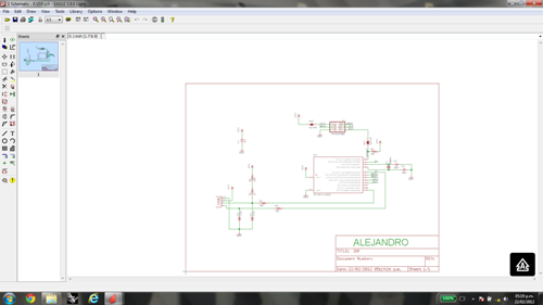
I selected one of the Fab ISP diagrams sent us for this task. First, I had to identify the components and drawn the diagram using the Eagle software
I want to recommend at this time to have special care in the location of the components as diodes and microcontrolers indicated on the scheme.
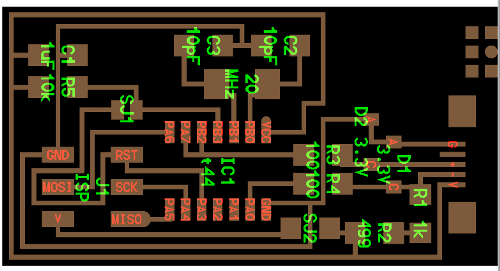
We need to chose the correct layer of the diagram for having the black zone to be machined by the miling machine. Likewise we must to separate the board once made the interior milling.


The board was manufactured using the Modela Roland milling machine where it was necesary to set some parameters of machining as cutting speed and depht
If we do not set the correct parameters of machining we would take the risk of breaking the tool because the tool is very thin. It was used 2 differents tools, the 1/64" tool for milling the board and the 1/32" tool for separating (cut) the board

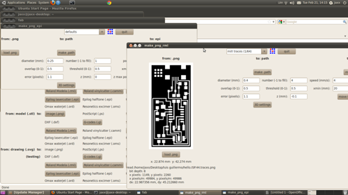
After setting all the parameters necesary to operating the milling machine began the milling process taking being careful not to leave the process without any supervision
I had some problems with the machining process by not fixing the plate following the correct procedure then the board was bent upwards arch and the milling was not perfect. In this process it has to set the "zero" point with the tool above the top of the plate.
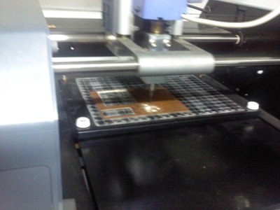
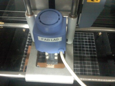
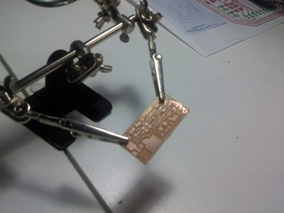
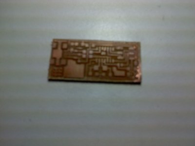
As you can see the board was not completely machined in one of their corners so I had to finish removing the excess but I managed it without problems
Selecting all the component putting them on a piece of paper with a regarding label for each one. Aside it is showing some elemens that helped me to complete
the assembling of the board
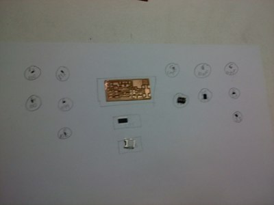
Really this was my first time that I made my own board and I think it was a good performance. Now I need to check that every component has been well soldered
As we can see in the next picture I am testing the board checking its correct assembly
Pending only the programming of the board that for lack of time was not completed today but tomorrow I must conclude it.
Programming the FABISP
Following the tutorial for programming in UBUNTU first I had to oinstall avrdude and GCC opening the terminal and typing
sudo apt-get install flex byacc bison gcc libusb-dev avrdude
sudo apt-get install gcc-avrIn my case the system asked me to type "y"
sudo apt-get install avr-libc
sudo apt-get install libc6-dev
Downloading and unziping the Firmware
cd ~/Desktop
wget http://academy.cba.mit.edu/classes/embedded_programming/firmware.zip
unzip firmware.zip
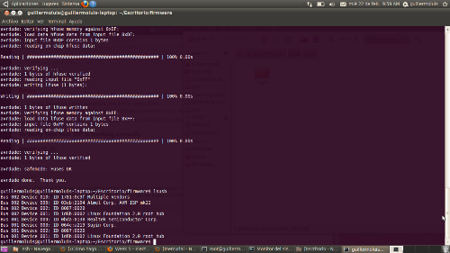
for programming the board we used the AVRISP and after connecting it to the board I checked the bad mounting seing the hated red and yellow lights what obey
me to find and correct 2 bad soldered joints in the microcontroller and the bridge. Once corected the errors I type
sudo make clean
sudo make hex
sudo make fuse
sudo make program
Finally after programming open the SJ1 and SJ2.
