Welcome to my "final project" page, below you'll find the design files and a description of the design and build process
Mechanical BOMI decided to build my winder out of wood, since wood is an easily sourced material all over the world and it's dirt cheap usually. The winder itself is built from 6mm multiplex since that was what was on hand at the time at the fablab. Later i learned that 6mm is not a standard size at most wood shops. So incidentally carriage and winder guide are made out of 4mm mdf. The type of material is not really important however i found that mdf is a little easier to laser, but multiplex is a nicer looking and sturdier material, however it is a tad bit more expensive. Also note that if you use a lower wattage laser cutter with 6mm multiplex, you might need to laser it twice to fully cut the material like i had to do. The width of the design was more or less arbitrarily chosen and unless you want to wind big wide coils you could easily scale the design down. I chose a width of 350mm because that was what i had chosen when ordering the polished rods and it seemed a good size at the time. My intention was to keep build cost under 200 euro's. In the end the total cost was less than 150 euro's.
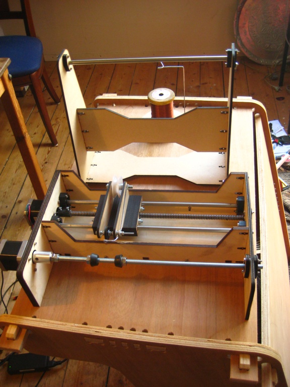
the basis of the woodjoints are inspired by the ultimaker of which we had 2 present at the fablab in Amsterdam. The combination of woodtabs to align the parts and M3 bolts/nuts provides a simple and sturdy build. For the carriage i used simple polished rods/linear bearings and a trapezoid lead screw design which was inspired by the MTM snap and other cnc designs. In essence this is a 2 axis CNC machine; one Y axis and one rotational axis. It should be possible to easilly replace the pulleys of the carriage with a pen or marker to make a small printer or something similar to an eggbot.
The carriage is constructed in layers out of 4 mm mdf and held together by 2 threaded rods (M6) fixed by two nuts. At first i wanted to 3d print the carriage, but after several attempts to print the 2 parts and 3 frustrating days later, i redesigned the carriage to be laser cut and made out of layers of 4mm mdf. The problem with 3d printing was that since the print was rather large the printer would stop extruding half way, rendering my print useless. I really like 3d printing, but using an ultimaker is far from a set and forget machine. It really requires a lot of experimenting with feed rates, fill pattern, temparature, etc. Unless you get really up close and personal with such a machine, you're going to have a hard time... Since we were pressed for time and i wasn't the only one using the machine i abandoned the idea of printing it. Unfortunatly my phone got stolen a few weeks back so i have no picture of the failed carriage print
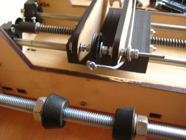
The carriage contains 4 lm8uu linear bearings and 2 trapezoid nuts separated by a spring (one nut is fixed with epoxy) to minimize backlash. When assembling the carriage the lead screw should first be threaded through the first (not fixed) nut, then this nut should be pushed towards the other (fixed) nut, compressing the spring. While holding the spring in it's compressed state the lead screw should be pressed through the other nut. This will enable the Anti-Backlash mechanism. The spring will always push the nuts against the threading of the leadscrew and therefore any backlash will be minimised. The resulting mechanism now works a follows: the lead screw has a threading of 3mm per rotation and the stepper is capable of 200 steps per revolution. Because the stepper driver has half stepping enabled we get 400 steps per revolution for the stepper. So if we divide 3mm / 400 = 0.0075 mm. So the theoretical resolution is 0.0075mm. In practice this mechanism worked pretty well. I used a micrometer measurement clock to measure going forward and back by the same amount and it would return with an accuracy of +/-0.001mm. Pretty good for an improvised anti backlash mechanism. The leadscrew was cut to length and milled on a lathe to get a 8mm ending to fit inside the ball bearing and on the other side to 6mm to fit inside the coupler.
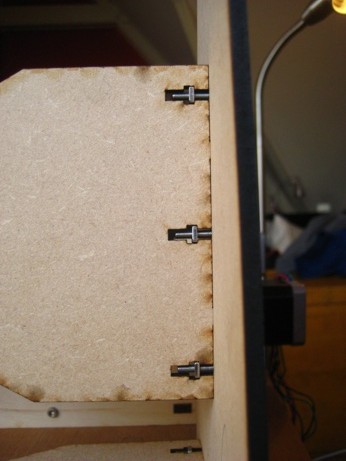
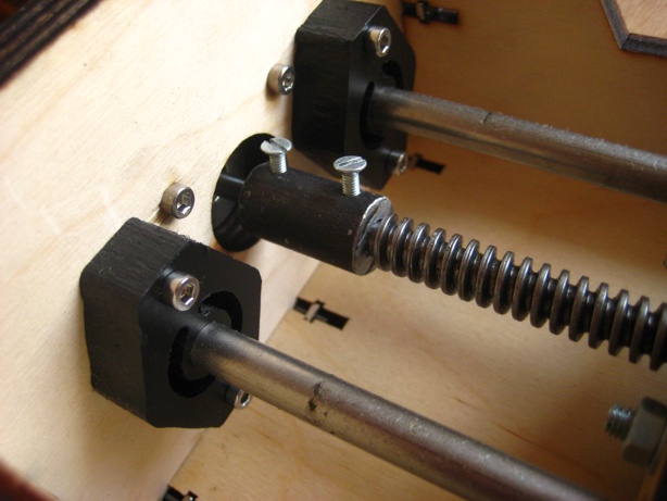
I used 12mm HDPE milled on the shopbot to hold the polished rods in place. The inside of the "rodplates" are hollowed out as can be seen 4 photo's below. Again this is something i borrowed from the MTM Snap. It enables the assembler to ensure both rods are as parallel as possible. The trick works as follows: Once you have the winder assembled, you heat the HDPE "rodplates" with a heatgun and you move the carriage around. Any friction will force the polished rods to stay parallel. Once the HDPE cools it stays in that position. In the end this was not needed and the carriage could easilly slide back and forth.
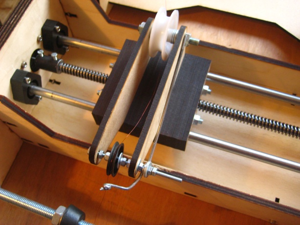
On the carriage i installed 2 pulleys to guide the wire, one big (to make it easier for the wire to follow it) and one smaller (to guide it better on the Bobbin). In the end i added a piece of polished steel rod, bent to an "as small as possible diameter" wire guide. I did this because the wire would tend to bunch up in one spot and because the last pulley was still too far from the bobbin and thus would not always follow the carriage properly. The wire guide was made from some spokes from a bike that i polished with brasso (metal polish) and then bent by hand in a vice with the help of some round pliers. The wire Despooler was made in the exact same fashion. Do Make sure when bending the steel that there a absolutely NO burrs or sharp edges. It took me a couple of tries to bend it the way i wanted it and keep it burr free.
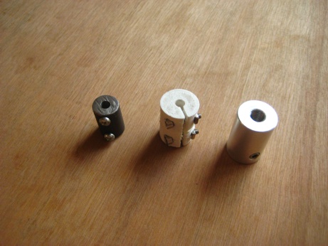
The coupler in between the position stepper motor and lead screw i made from a piece of round staff steel on the lathe at Fablab Amsterdam. This was my first time operating a lathe and the result was moderately ok for this purpose. For the coupler of the winding motor i first anticipated to use only one point to fix the threaded rod on the winding stepper motor but this turned out to be a HUGE mistake. The threaded rod would wobble enormously. At first i thought this was due to my not so present skills on the lathe. I also tried making a coupler on the 3D printer, but this failed for the same reason as my carriage; the printer would stop extruding half way through. After a couple of tries i finaly got a workable print, but in practice the coupler would not hold properly and was very brittle. Because it was so brittle i could not put enough tension on the shaft to hold it and it would result in lost windings. so instead of buying one i had my neighbour (peter moll website Thanks Peter!) make me a coupler. He also came up with the idea of threading the inside of one side of the coupler and using a counter nut to fix the threaded rod, which helps easy removal tremendously. This coupler was a lot better (understatement!), but the axis would still wobble since the threaded rod was not perfectly straight. So i adapted the design to have a support with a ball bearing on the other side of the winding stepper motor to provide less degrees of freedom for the rotational axis. However removing the bobbin now requires you to remove the threaded rod from the coupler and sliding it through the ball bearing to release the bobbin. A tedious job, but it works. Peter is at the moment teaching me how to operate his lathe and i'm reading "the amatuer's lathe" (1948) from Lawrence h. Sparey, Which imo is one of the best books of the subject and should be part of any fablab which has a lathe present.
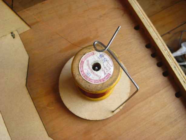
Since it is neccesary for the wire to come from above to the first pulley on the carriage, i also constructed a wire guide out of 4 mm mdf and the leftover from my polished rod. And i made a wire despooler, in the same fashion as the wire guide on the carriage, to avoid uncontrolled despooling. Both helped with despooling the wire and tensioning the wire. However the operator still needs to provide some tension on the wire otherwise the mechanism will not operate properly and the wire will get caught between the pulleys of the carriage and will break very easily. A much needed upgrade for the coil winder would be a properly designed wire tensioning device. I did not get involved with a wire tensioning device because of a lack of time and i could not find any documentation on how to constuct such a device. I also did not buy a wire tensioning device since even the simplest commercial wire tensioner costs a multitude of the total cost of this winder and of course it would not be open source...... It's on the todo list.
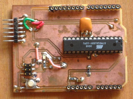
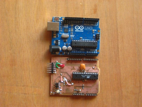
For the electronics i needed; a microcontroller, 2 stepper drivers + stepper motors and a user interface. For testing i used a arduino, i knew this was not allowed by Neil.... so i made a fabable arduino. It's based around a atmega168/328p 28 pin dip version since that's what i had at hand at home at the time. It's a double sided board with all pins broken out to the standard arduino form factor. The nice thing about it is that it's 100% compatible with standard arduino shields, which i haven't seen in any fabable arduino's. It has a ftdi and isp header and can be programmed via the arduino ide after you flash the bootloader with a isp programmer. It also supports auto reset. Only thing that is missing is a regulator and power jack, but it uses the ftdi cable as powersource.
Do note that when done with milling out the top traces, mill the square outline first and then mill out the arduino shape. Otherwise it will be impossible to flip the board due to the irregular shape! I only noticed this when i did my first prototype and i had to quickly make the square milling outline to save my board.
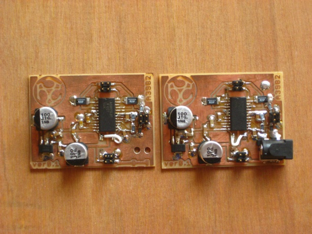
next up is a single stepper motor driver i made based around the allegro A3982 chip. The board features pull down resistors on the DIR and STEP pins so the motors won't randomly step if you reset the microcontroller. It also has power input for the motor power and a 5V regulator to power the chip. Multiple stepper boards can be daisy-chained for power. I made judicious use of decoupling of the power supply to avoid false triggering of the DIR and STEP functions. R3 and R4 form a voltage divider that set the maximun motor current, they both specified at 10K which results in a voltage of 2.5V on the REF pin of the 3982. At first i i used the same resistors as the MTM snap motor shield (4.99K to 5V and 1K to gnd), however this provided insuffiecient torque to move my motors. Which might have been due to me using a 19V power supply instead of them using a 24V power supply. A higher voltage power supply could be easily used. The datasheet specifies a max motor Voltage of 35V. Upping the voltage would lead to higher torque on the motors but care must be taken not to burn out the stepper motor so do check the datasheet for the motors you will be using. And adjust R3 and R4 accordingly. The Calculation needed to set the current can be found in the Allegro A3982 Datasheet
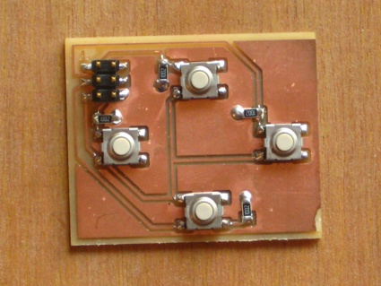
Last board i made was the ui board which is a very simple board with 4 buttons and it's respective step down resistors.
CoilWinder source code
/*
Coil winding sketch made for use with Thomas Hopman's FabAcademy 2012 final project; a open source cnc coil winder.

created by Thomas Hopman

This software may be modified and used freely for non-commercial and personal use
for commecial licences contact Thomas Hopman @ sureshotstudio@gmail.com

last modified: 29 may 2012
*/

#include <Bounce.h>
// setup pins
int dirPin1 = 2;
int stepperPin1 = 3;

int dirPin2 = 4;
int stepperPin2 = 5;

int buttonPin1 = 6;
int buttonPin2 = 7;
int buttonPin3 = 8;
int buttonPin4 = 9;

int limitSwitch1 = A0;
int limitSwitch2 = A1;

// setup variables
int resolution = 400;
int resolutionW = 10;
int done = 0;
float WireSize = 0.01;
unsigned long windings = 10;
float width = 0.1;


// setup debouncing for the push buttons
Bounce bouncer1 = Bounce( buttonPin1,2 );
Bounce bouncer2 = Bounce( buttonPin2,2 );
Bounce bouncer3 = Bounce( buttonPin3,2 );
Bounce bouncer4 = Bounce( buttonPin4,2 );

void setup() {
  // Setup serial connection
  Serial.begin(115200);

  // Setup pins
  pinMode(dirPin1, OUTPUT);
  pinMode(stepperPin1, OUTPUT);
  pinMode(dirPin2, OUTPUT);
  pinMode(stepperPin2, OUTPUT);

  pinMode(buttonPin1, INPUT);
  pinMode(buttonPin2, INPUT);
  pinMode(buttonPin3, INPUT);
  pinMode(buttonPin4, INPUT);

  pinMode(limitSwitch1, INPUT);
  pinMode(limitSwitch2, INPUT);
}
// Stepper functions
void step3(unsigned long NumWindings, float BobbinWidth, float SizeWire) {

  //Calculate setup values
  unsigned long steps = NumWindings * 400; //calculate the total number of steps needed for this wind. Max number windings possible is 10 737 418.2 = <max unsigned long size> / 400
  float subSteps = SizeWire / 0.0075; // calculate after how many winding steps the wire position stepper needs to advanced ONE step.
  unsigned long SubDiv = 400 / subSteps; // part of above calculation
  unsigned long BobbinTravel = (BobbinWidth / 0.0075); //Calculate after how many steps the position stepper needs to reverse direction
  unsigned long DirCounter = 0; // reset DirCounter
  boolean Dir = true; // reset Dir

  // Setup default directions
  digitalWrite(dirPin2,false);
  digitalWrite(dirPin1,Dir);
  delay(50);

  //Debugging stuff
 /*
  Serial.print("NumWindings = ");
  Serial.println(NumWindings);
  Serial.print("BobbinWidth = ");
  Serial.println(BobbinWidth);
  Serial.print("SizeWire = ");
  Serial.println(SizeWire);
  Serial.print("steps = ");
  Serial.println(steps);
  Serial.print("subSteps = ");
  Serial.println(subSteps);
  Serial.print("SubDiv = ");
  Serial.println(SubDiv);
  Serial.print("BobbinTravel = ");
  Serial.println(BobbinTravel);
  delay(1000);
  */

  //Start winding
  for (long x = 0; x < steps; x++)
  {
    digitalWrite(stepperPin2, HIGH);
    delayMicroseconds(250);
    digitalWrite(stepperPin2, LOW);
    if (x % (SubDiv + 1) == SubDiv) // if; advance the position stepper when needed. else; delay 250 to settle the stepperPin2 Low value on the stepper driver.
    {
      if (DirCounter == BobbinTravel) // if DirCounter exceeds the max bobbintravel set direction is reversed and DirCounter is reset.
      {
        DirCounter = 0;
        Dir = !Dir;
        digitalWrite(dirPin1,Dir);
        delayMicroseconds(100);  // wait 100 milliseconds for the direction setting to settle on the stepper driver

      }
      digitalWrite(stepperPin1, HIGH);
      delayMicroseconds(250);
      digitalWrite(stepperPin1, LOW);
      DirCounter++;

    }
    else
    {
      delayMicroseconds(250);
    }
  }
}

void step1(boolean dir,int steps) // funtion used for testing. For instance this function can be used to hard code the max possible speed for your stepper motor/driver combo by hard coding the delayMicroseconds()
{
  digitalWrite(dirPin1,dir);
  delay(50);
  for(int i=0;i<steps;i++){
    digitalWrite(stepperPin1, HIGH);
    delayMicroseconds(250);
    digitalWrite(stepperPin1, LOW);
    delayMicroseconds(250);
  }
}

void step2(boolean dir,int steps) //function used for spooling wire slowly!
{
  digitalWrite(dirPin2,dir);
  delay(50);
  for(int i=0;i<steps;i++){
    digitalWrite(stepperPin2, HIGH);
    delayMicroseconds(2000);
    digitalWrite(stepperPin2, LOW);
    delayMicroseconds(2000);

  }
}

void loop(){

  /**************************************************************************************************************************************************************************************/
  delay(300);

  // print instructions
  Serial.println("Press left or right to set start of coil (1 press = 3 mm = 400 steps). Press down to set resolution. Press up when done");

  // while loop to set "Home"
  while(done == 0) {

    // update the debouncer
    bouncer1.update ( );
    bouncer2.update ( );
    bouncer3.update ( );
    bouncer4.update ( );

    // get the update values
    int up = bouncer1.read();
    int right = bouncer2.read();
    int down = bouncer3.read();
    int left = bouncer4.read();


    // move stepper 1 rev in the right direction
    if ( up == HIGH ) {
      //step2(true,400);
      Serial.println("Home is set, Thank You.");
      Serial.println();
      //resolution = 400;

      done = 1;
      delay(400);
    }

    if ( right == HIGH ) {
      step1(true,resolution);
      delay(100);

    }

    if ( down == HIGH ) {
      resolution = resolution - 25;
      if ( resolution == 0) {
        resolution = 400;
      }
      Serial.print("resolution = ");
      Serial.print(resolution);
      Serial.print(" = ");
      Serial.print(0.0075 * resolution);
      Serial.println(" mm");


      delay(400);
    }

    if ( left == HIGH ) {
      step1(false,resolution);
      delay(100);
    }

  }

  delay(400);


  /**************************************************************************************************************************************************************************************/

  // print instructions
  Serial.println("if needed advance the winding motor by pressing left or right to spool on some wire. Press up when done");

  // while loop to spool on some wire
  while( done == 1 ) {

    // update the debouncer
    bouncer1.update ( );
    bouncer2.update ( );
    bouncer3.update ( );
    bouncer4.update ( );

    // get the update values
    int up = bouncer1.read();
    int right = bouncer2.read();
    int down = bouncer3.read();
    int left = bouncer4.read();


    //
    if ( up == HIGH ) {
      Serial.println("Spooling is done, Thank You.");
      Serial.println();

      resolution = 400;
      done = 2;
      delay(400);
    }

    if ( right == HIGH ) {
      step2(false,resolution);
      delay(100);

    }

    if ( down == HIGH ) {
      resolution = resolution - 5;
      if ( resolution == 0) {
        resolution = 400;
      }
      Serial.print("resolution = ");
      Serial.print(resolution);
      Serial.print(" = ");
      Serial.print( resolution * 0.0025 );
      Serial.println(" revolution");


      delay(400);
    }

    if ( left == HIGH ) {
      step2(true
      ,resolution);
      delay(100);
    }
  }


  /**************************************************************************************************************************************************************************************/

  // print instructions
  Serial.println();
  Serial.println("Please enter number of windings. Right for more, Left for less. Up for done (please take into account the number of windings done during spooling!!!!!)");

  while ( done == 2) {

    // update the debouncer
    bouncer1.update ( );
    bouncer2.update ( );
    bouncer3.update ( );
    bouncer4.update ( );

    // get the update values
    int up = bouncer1.read();
    int right = bouncer2.read();
    int down = bouncer3.read();
    int left = bouncer4.read();

    if ( up == HIGH ) {
      Serial.print("Number of windings is set to ");
      Serial.print(windings);
      Serial.println(" ,Thank You!");
      Serial.println();

      done = 3; // break while loop
      delay(400);
    }

    if ( left == HIGH ) {
      windings -= resolutionW
      ;
      if (windings <= 0) {
        windings += 10;
        Serial.println("windings can not be 0 or lower!");
        delay(100);

      }
      Serial.print("windings = ");
      Serial.println(windings);
      delay(100);
    }

    if ( down == HIGH ) {
      resolutionW = resolutionW - 9;
      if ( resolutionW < 0) {
        resolutionW = 10;
      }
      Serial.print("resolution = ");
      Serial.print(resolutionW);
      Serial.println(" windings");

      delay(400);
    }

    if ( right == HIGH) {
      windings += resolutionW;
      Serial.print("windings = ");
      Serial.println(windings);
      delay(100
      );
    }
  }

  /**************************************************************************************************************************************************************************************/

  // print instructions
  Serial.println();
  Serial.println("Please enter wire size. Right for more, Left for less. Up for done.");

  while ( done == 3) {
    // update the debouncer
    bouncer1.update ( );
    bouncer2.update ( );
    bouncer3.update ( );
    bouncer4.update ( );

    // get the update values
    int up = bouncer1.read();
    int right = bouncer2.read();
    int down = bouncer3.read();
    int left = bouncer4.read();

    if ( up == HIGH ) {
      Serial.print("wiresize is set to ");
      Serial.print(WireSize);
      Serial.println(" ,Thank You!");
      Serial.println();

      done = 4; // break while loop
      delay(400);
    }

    if ( left == HIGH ) {
      WireSize -= 0.01;
      if (WireSize <= 0) {
        WireSize += 0.01;
        Serial.println("wiresize can not be 0 or lower!");
        delay(100);
      }

      Serial.print("wiresize = ");
      Serial.println(WireSize);
      delay(100);

    }

    if ( right == HIGH) {
      WireSize += 0.01;
      Serial.print("wiresize = ");
      Serial.println(WireSize);
      delay(100);
    }
  }

  /**************************************************************************************************************************************************************************************/

  // print instructions
  Serial.println();
  Serial.println("Please enter bobbin width. Right for more, Left for less. Up for done.");

  while ( done == 4) {
    // update the debouncer
    bouncer1.update ( );
    bouncer2.update ( );
    bouncer3.update ( );
    bouncer4.update ( );

    // get the update values
    int up = bouncer1.read();
    int right = bouncer2.read();
    int down = bouncer3.read();
    int left = bouncer4.read();

    if ( up == HIGH ) {
      Serial.print("width is set to ");
      Serial.print(width);
      Serial.println(" ,Thank You!");
      Serial.println();

      done = 5; // break while loop
      delay(400);
    }

    if ( left == HIGH ) {
      width -= 0.1;
      if ( width <= 0 ) {
        width += 0.1;
        Serial.println("bobbin width can not be 0 or lower!");
      }
      Serial.print("bobbin width = ");
      Serial.println(width);
      delay(100
      );

    }

    if ( right == HIGH) {
      width += 0.1;
      Serial.print("bobbin width = ");
      Serial.println(width);
      delay(100);
    }
  }

  /***********************************************************************************************************************************************************************************/

  // print instructions
  Serial.println("Setup summary.");
  Serial.print("windings = ");
  Serial.println(windings);
  Serial.print("wiresize = ");
  Serial.println(WireSize);
  Serial.print("bobbin width = ");
  Serial.println(width);
  Serial.println();
  Serial.println("Do you want to commence winding with these settings?");
  Serial.println("press up to commence, press down to change settings, press right to purge settings and start again");


  while ( done == 5 ) {
    // update the debouncer
    bouncer1.update ( );
    bouncer2.update ( );
    bouncer3.update ( );
    bouncer4.update ( );

    // get the update values
    int up = bouncer1.read();
    int right = bouncer2.read();
    int down = bouncer3.read();
    int left = bouncer4.read();

    if ( up == HIGH ) {
      Serial.println("winding will commence in....");
      delay(1000);
      Serial.println("3....");
      delay(1000);
      Serial.println("2....");
      delay(1000);
      Serial.println("1....");
      delay(1000);
      Serial.println("winding will start now");
      Serial.println();
      step3(windings, width, WireSize);
      delay(1000);
      Serial.println("Done winding");
      Serial.println();

      delay(100);
      done = 0;
    }

    if ( down == HIGH ) {
    delay(100);
    done = 0;
    }

    if ( right == HIGH ) {
      Serial.println("settings are being reset");
      WireSize = 0.01;
      windings = 10;
      width = 0.1;

      delay(100);
      done = 0;
    }
  }
}
The software for this machine is very simple. If you look at the source code you will find that 90% of the code is for the GUI which is presented to the user via a serial terminal (115200). The source can be downloaded via the link above or copy pasted from below.
It works as follows. First the software will ask you to set the carriage to the start of the bobbin. The movement of the carriage is in steps, but the steps can be set by pressing down. once done you will need to press up. Next it will ask if you want to spool on some wire to the bobbin. Again press up for done. After that you can set the wire size, bobbin width and the number of windings needed. All with the basic set of commands: left, right for less or more respectivly, down for resolution and up for done. After all is setup you can either go back to change any settings or commence winding.
As of yet the software is very simple and does not support ramping and a kill/limit switch interrupt. So if the wire breaks during a wind you will either need to cut power or reset the arduino to avoid waiting for the entire winding process to finish, this does however reset all the winding settings. To set the speed of the winding process you can hard code the delay in the step3() function. With my particular stepper motor/driver combo the minimum delayMicroseconds needed was 200. Anything below and there was not enough torque for advancing of the motor. Higher values are recommended to not lose any steps and/or lose windings. I found that 250 microseconds was a nice compromise between speed and torque. Alternatively you could try increasing the Voltage and Amps fed to the stepper motor driver to be able to increase speed and torque.
When i have time after the academy i will try to setup a public wiki and upload all the files to thingiverse so hopefully other people can benefit from or build on my design. details will of course be posted here
This week i've started turning the design files in to reality. Laser cutting of the chassis is done + milling of the threaded rods and rod plates. Most of the ordered parts have come in and assembly has commenced. I've had a couple of iterations of the carriage design and tried to finalise the design.
what will it do?
For my final project i am designing a coil winder. This machine will be designed to wind inductor coils from enamel covered copper wire on to plastic bobbins. I should do the winding all by itself after the user sets up the machine. Number of turns and the distribution of the wire onto the bobbin will be taken care of by the machine.
who's done what beforehand?
There are quite a few machines available for winding inductor coils. From DIY hand cranked jigs to Full on industrial winding machines. Here is a list of links to some of the machines available.
what materials and components will be required?
where will they come from?
how much will it cost?
A preliminary Bill of Materials can be found here including pricing and suppliers. This list will be updated regularly as the project will progress. Right now the total projected cost will be between 130 to 200 euro for the entire machine including electronics.
what parts and systems will be made?
The electrical system will be a microcontroller for driving 2 stepper motors and communication to a host computer. Also it will need to interface to 2 end-stop switches.
The software system will be used to calculate the control signals for the amount of turns needed on a particular bobbin with a certain diameter of wire.
what processes will be used?
Laser Cutting of the frame, CNC Milling for the hdpe rodplates, 3D Printing of the carriage and Hand operated Lathe Milling for turning the lead screw and making of the couplers. Alternatively i can make the couplers on a 3d printer.
what tasks need to be completed?
A Lot! The design will need to be finalised, made, tested. And then the software will need to be written. Alternatively i can use available open source software.
what questions need to be answered?
I have yet to design and construct a system for automatic tensioning of the magnet wire. Also a system for guiding the wire on the carriage will need to be devised.
what is the schedule?
This week the frame and the mechanical construction will be made. Lathe milling of the lead rod and construction of the shaft couplers. At the same time a wire feeding and guiding system will be finalised and tested. Most parts have been arrived and some parts are expected to arrive this week.
next week the electrical system will be made and the software will be made and finalized. The mechanical system will tested and finalized and if needed modified.
The week after there should be a beta version finalised and further improvements will be made to have at least a workable machine.
how will it be evaluated?
The machine should be able to automatically wind a coil with minimal intervention from the user.
this project will consist of 3 stepper motors: one for turning the bobbin, one for guiding the magnet-wire laterally on the bobbin and one motor for feeding the wire. All this will be controlled by a microprocessor with a UI (LCD Screen with buttons) or a computer connected to a microprocessor. Also i will need to find a way to feed the magnet-wire and put constant tension on it without breaking the wire. A very very very rudimentary sketch can be found here.
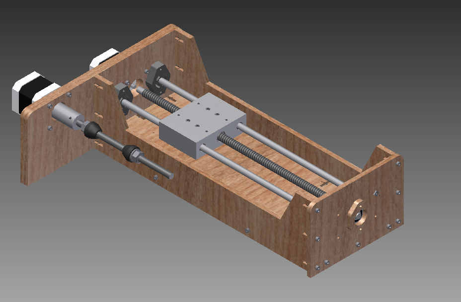
A little more progress. I've battled with quite a few 3D programs over the course of the week. Finally 2 days ago i settled on Autodesk Inventor (be sure to check out their free software program for students) since i couldn't find a student trial version of rhino (trail limited to 25 saves). No animation yet but here is a pdf of my home view ----> LINK.
last updated 23 May 2012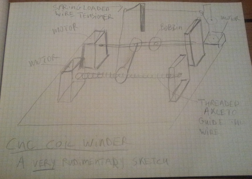