Molding with wax et al
I have had to struggle with Google Sketch Up ®!!
My result was as always to produce a functioning object, however due to what I envisaged as being straight forward was anything but.
I had wanted to mold draws for my storage unit made for the "Make something Big" assignment.
Due to size, complexity and deadline, this was not feasible, I had a rethink and decided on molding some endcaps for a storage tube for my portable antennas again this was deemed beyond the scope of this assignment. After much deliberation and just to satisfy the requirements and post this page in time for Wednesday next I have opted to make a simple plaque.
Callsigns
Each amateur or professional radio station has its own unique identity , these are known in the radio fraternity as Callsigns or Calls. These are issued by the appropriate Government in the UK the Department is called OFCOM in the US the FCC.
Each country has a "Prefix" which sets not only the country of origin in my case M (others for the UK are G or 2E) and the class of license I have a full license my class is 1. The "Suffix" is the last 3 letters which tell the year of issue and how many licenses were issued.
My callsign is M1BPT
Google Sketch Up Version 8 ®
Within the GUI extended toolset, There is a tool available to place text as a 3D Model. I used this as shown below to create my Callsign (M1BPT)
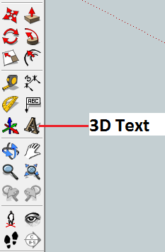
Using the 3D Tool to input M1BPT
Upon selection there is a multifunctional dialogue box displayed in the GUI. This allows the actual text required to be input , The font face the size of font in millimetres and both the text alignment and the level of extrusion as shown below: 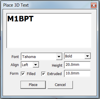
Input shown as a 3D Model
Below is the result of imputing data into Google Sketch Up ®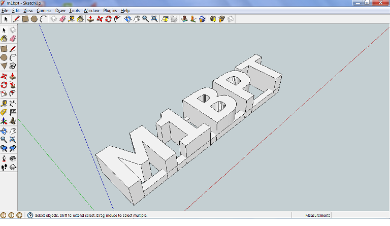
As all the Alphanumerics would be separate objects and this model was to be a mold for casting it was necessary to put supporting pieces in the model to make the letters and numbers as one piece.
This was archived by drawing two intersecting lines at right angles from the bottom right hand face of the letter "M" and using the Push/Pull tool dragging the resultant face through the bottom of the whole piece,for extra stability the process was repeated at the top of the piece.
The project as exported by Google Sketch Up ® as shown as a 2D graphic in .png format is shown below: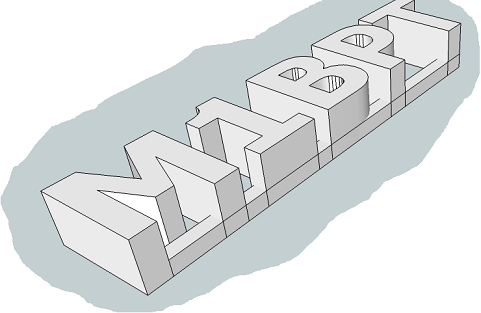
Exporting from Google Sketch Up ®
Google Sketch Up ® does not directly support either working in either .dxf or .stl files , this is archived by installing a tool written in Ruby Script. This may be downloaded from :
http://www.guitar-list.com/download-software/convert-sketchup-skp-files-dxf-or-stl
Loss of Accuracy
A concern in using multiple programmes to create a product is the algorithms used to allow the flows of data to replicate with certain accuracy all the attributes of a physical object in the output.
Below is a snapshot of the source code for the skp to dxf or stl
Looking into the discrepancies in resulting read ins and interpretations are beyond the scope of this assignment, suffice to say that for true precision the software should be both bespoke and direct output in the language of the output device.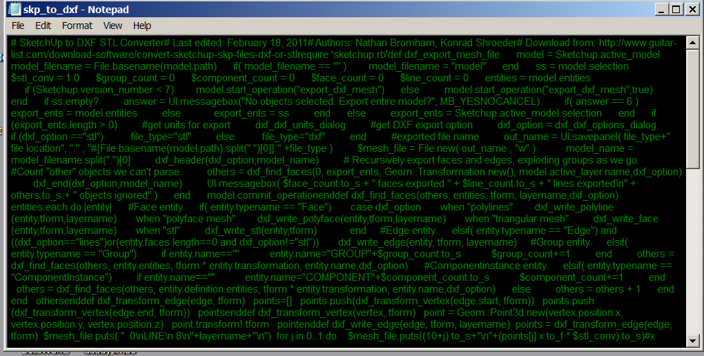
To export the model as a stl file the conversion / export plug-in is not standard
The .rb file needs to be manually copied to the tools directory. In Windows 7 ®
This is found in C:\Programs (x86)\Google\GoogleSketchUp 8\Tools
The process is initiated by clicking the appropriate tab in the Google Sketch Up ® Tools menu as shown below: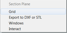
The Workflow so far
1. Create a 3D solid in Google Sketch Up ®
2. Export your model from SketchUp to a.stl file, using the free DXF/STL Exporter plugin.
3. Convert the STL file to a file compatible with your output device(in our case the Roland Modela 20).mpj file.
more can be found out about the Modela at the Manchester FabLab Website at : http://www.fablabmanchester.org/p31/Roland-Modela-MDX-20-Desktop-Miller.html
Below the Roland Modela MDX 20 ®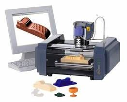
Roland Modela Player 4
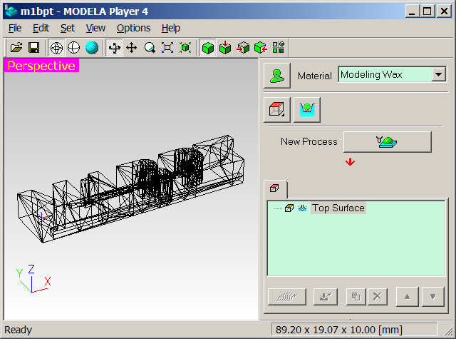
The stl file is imported into the Controlling software for the MDX 20. The GUI prior to importing is shown below: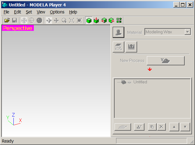
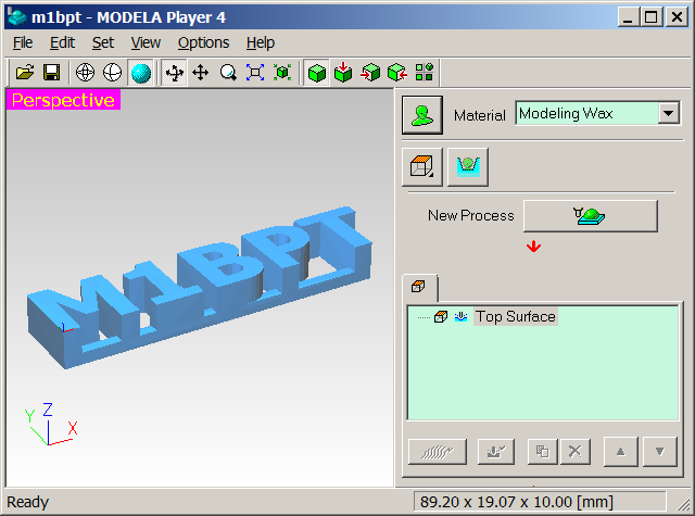
The Resulting import with rendering applied is shown below:
It is at this point that we define new tools for using on the wax blocks.
Tool Profiles
Below is a side profile of the two Modela ® tools :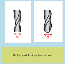
From the above patterns of tools , it should be noted that if the output of the job has curved surfaces then 2 separate tools will need to be associated with the job; as the finishing requires the use of a "Ball" tool. If not all processes can be associated with the same tool, which is advantageous as no tool changes are required and subsequently less ajustment of the cutting head.
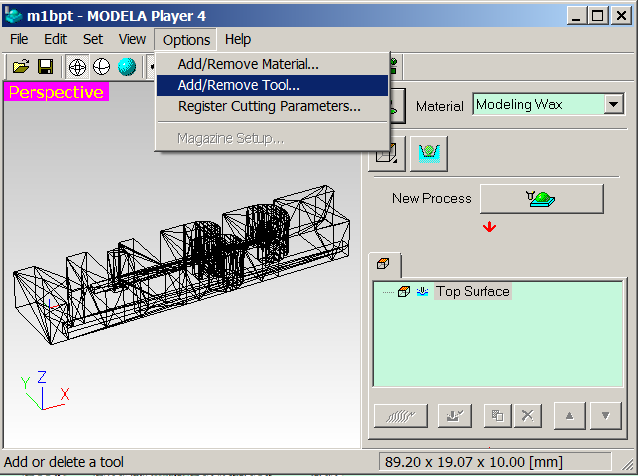
Below is shown the menu from the Modela Player 4 ® GUI
Wthin the player GUI this allows the addition of a new tool to the excisting libaries. New tools can be downloaded from the internet , however it is easier to look at the tool specification and data sheets and modify a copy of an excisting tool to the excisting selection of tools in this example two new tools are created 1 straight & 1 ball. of 1/8th of an inch imperial tool which equals 3.17mm diameter. The 3mm metric straight tool was copied and then edited. The example of the straight tool is shown below:
The dialoge box detaling the settings for the new tool is displayed.
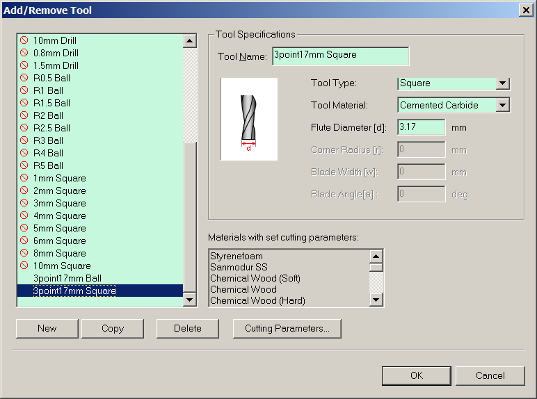
The settings checked and found to be correct for material and speed of cut, The dialoge allows completion of this step and its association to the new process. Process creation as a walk through is shown below:
The Process Setup for Modeling Wax on the Modela MDX 20 ®
Below is the work flow for the processes required for the Roland Modela MDX 20 ®
to machine modelling wax. For the process to be completed requires all parameters must be set before machining. Because of the complexity of the wizard GUI I have recorded this once as commented images. This routine needs to repeated for every process so a further
3 processes are required for the job to run to completion.
Associate the or excisting tool with the process
Workflow for the Milling of Modelling Wax
From a Blank GUI
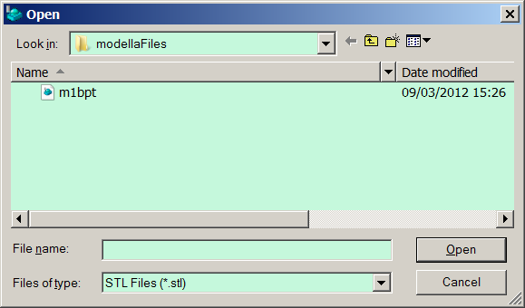
Step 1 Open Modela Project File .mpj
The Modela ® Requires a .stl extention file in this case the file is named m1bpt.stl
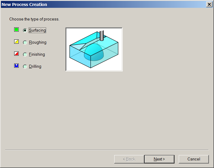
Step 2 Create New Process
Step 3 Select Class of Cut
There are 4 classes of cutting Surfacing , Roughing, Finishing & Drilling.
In this illustration surfacing is selected:
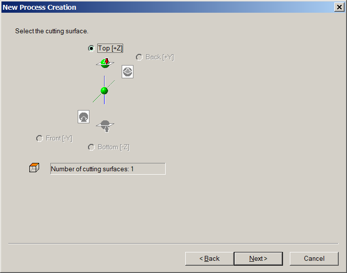
Step 4 Select number of cutting surfaces
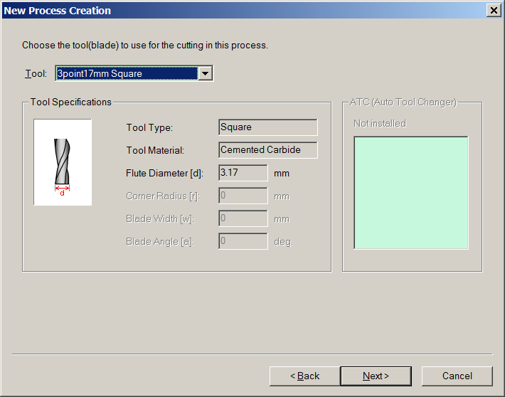
Step 5 Choose Tool
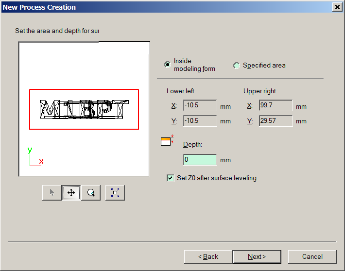
Step 6 Set Surface Area and Depth for Leveling
In this example the surface (skim) depth is 1mm . This levels the surface of workpiece:
Step 7 Choose Type of Toolpath
The Modela ® Model Software has various options of how the tool paths are defined such as "Contour" "X,Y" "X only" and "Spiral". Each has its own place and merits and are beyond the scope of this assignment . I am using "X,Y". This is shown below: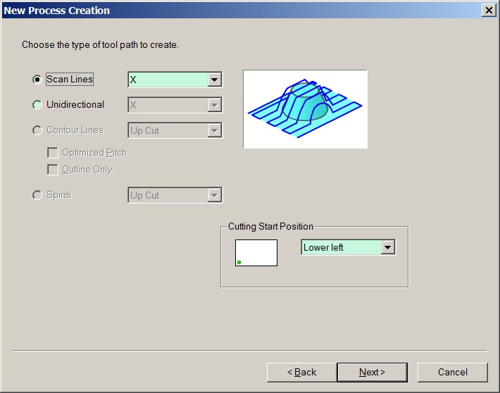
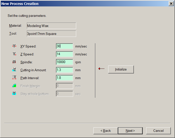
Step 8 Cutting Parameters (Tool Speed)
Below is the screen relating to the parameters of how the tool will cut on each pass.
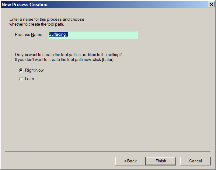
Step 9 Create & Name Tool Path
The Modela ® Software has a default naming convention of the type of process surface , rough , finish 1 , 2 & 3 etc . The Default for this process is "Surface1".
Step 10 Output of Tool Path
Below is the pattern the tool path will follow when cutting :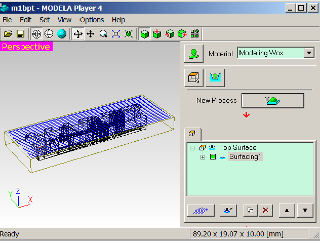
There can be as many as 46 steps in this workflow we now return to define the Roughing and Finishing and possibly Drilling.
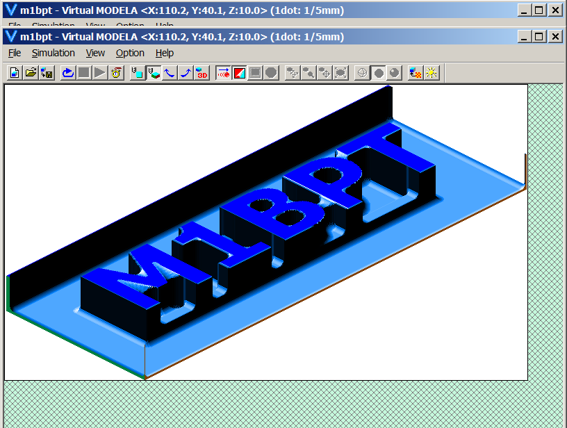
Below a simulation from Virtual Modela of the finished positive mold in modeling wax:
Molding in Silicon
Mixing Silicon
The silicon solution is a 2 part product the silicon is a viscose material plus with a separate curing agent.
The silicon is poured in to a disposable plastic beaker and weighed and add the extra 3% weight for
the curing agent.
The curing agent was drawn into a syringe and dripped into the silicon solution until the target weight is reached. The solution is mixed vigorously like egg meringue.
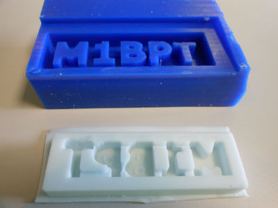
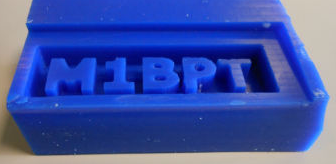
Below is shown the finished wax mold machined on the MDX-20
The Wax Filled with 100g of Silicon Curing
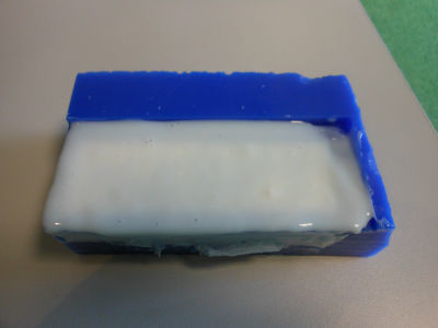
The finished silicon mold separated from the Wax Block