

A 3D scanner is a device that analyses a real-world object or environment to collect data on its shape and possibly its appearance (e.g. colour). The collected data can then be used to construct digital three-dimensional models.
Many different technologies can be used to build these 3D-scanning devices; each technology comes with its own limitations, advantages and costs. Many limitations in the kind of objects that can be digitised are still present, for example, optical technologies encounter many difficulties with shiny, mirroring or transparent objects. For example, industrial computed tomography scanning can be used to construct digital 3D models, applying non-destructive testing.
Collected 3D data is useful for a wide variety of applications. These devices are used extensively by the entertainment industry in the production of movies and video games. Other common applications of this technology include industrial design, orthotics and prosthetics, reverse engineering and prototyping, quality control/inspection and documentation of cultural artifacts. (1)
I decided to try three different 3D scanning methods.
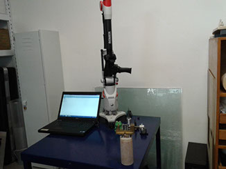
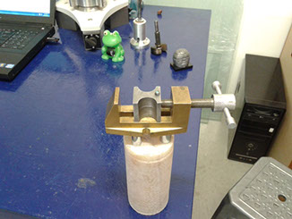
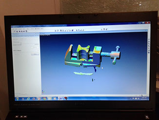
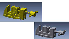
At Our lab we have an Hexagon Romer 3D laser Scanner. It is very precise but has the inconvenient that the part must be very still, any variation in the part's position results in abortion of the process
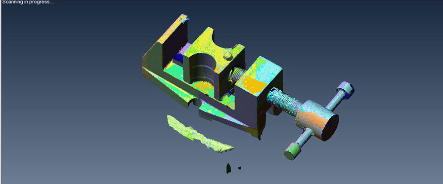
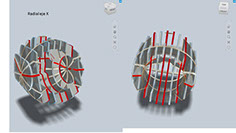
The laser looks like a line on the surface with a dot to focus the scanning.
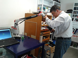
To successfully scan a part it is important to very slowly pass the laser line all over the object's surface with several passes, like if we were painting a surface with a painting gun, one pass at a time, otherwise there will be too many points in the point cloud making the archive heavy and many times less precise.
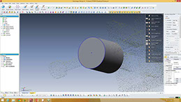
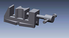
The finished scann can be seen in the picture of the right, it makes 1 544 000 triagles.
You can download the cloud point HERE
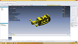
Reverse engineering. In Fab LAb Puebla we have Geomagic Design X software for reverse engineering. With some practice it is a very easy process where you select parts and surfaces and recreate the solids that form the piece.
It is a very powerful software that identifies must shapes and surfaces and helps to ease the process. The final result is a part engineered part with measures and tolerances.
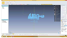
The first step is to open the exported cloud point. it accepts many formats the easiest is with a .txt archive.
After opening one must clean the cloud point for excess points
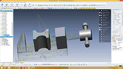
Once we have an optimized cloud point we have to make the surface and after that the software recognizes different surfaces in the scan
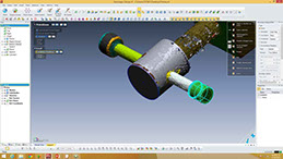
Next is to build the solid. There are many ways to do this, one is using primitive solids, the software recognize the solid and automatically builds it, you have to give minor adjustments. You can see part of the process in the second picture.
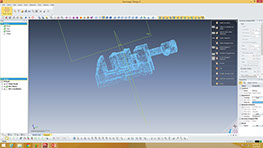
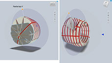
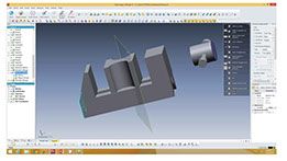
Another technique is to to choose a surface and build a plane on that surface, after that you move the plane inside the surface so you can have the form sketch as can be seen in right picture. We can modify the sketch to right measures and then extrude it to the chosen surfaces
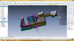
You end by building every solid in the part. The software has the ability to measure differences between the scan and the constructed solid
Finally you have an engineered part. With precise measures.
The laser 3D scanner is very precise machine and with the aid of a reverse engineering software in very little time one can have a final part with very precise measures ready for 3d print or other manufacturing process.
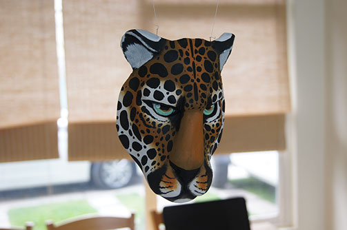
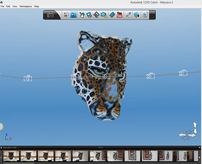
The second 3D scanning method I tried was 123D Catch. This software works with pictures and stitches them together to make a 3d scan.
You must have a very controlled light conditions.
The scan looks great, I think it is ideal for presentations but it seems that the mesh is not very detailed.
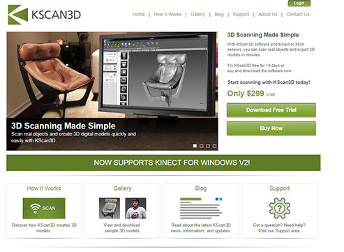
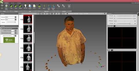
I also tried to scan myself with a Kinect device.
I used the Kscan 3D software. I find the device not very useful for 3D scanning. The results were very poor and it was difficult to align the different meshes created by hand
3D Printing
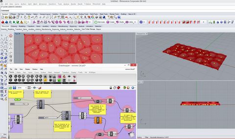
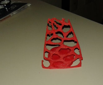
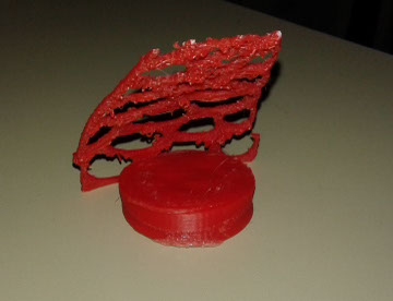
To make a 3D printed part that could not be done by subtractive methods I decided to build a surface with a Voronoi pattern embedded with Grasshopper, bake it, and then in Rhino I used the Blend and Twist commands to make a ceiling on top of a round surface.
On purpose I made it very hard to print, the Voronoi pattern surface was very thin and inclined. You can find the archive HERE.

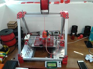
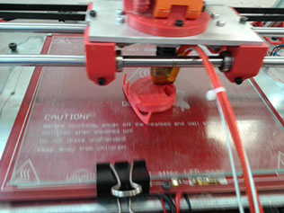
At Fab Lab Puebla we have several printers including a Dimension 1200 printer with support materia. The part can be very easily printed in it but I decided to print it in a printer made at Fab Lab Puebla, since we are testing the equipment
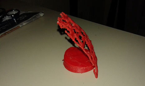
At the end I liked very much the finished product. Despite the problems in the design the machine did a very good job printing the part. Our team made several forms with much better results
1. Wikipedia