3D Scanning and Printing
Rotational Flexure Mechanism
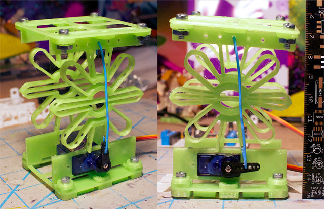
3D printed in PLA, actuated using a micro servo + paper clip:
Making Of
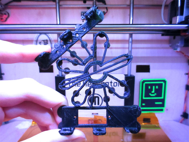
This design is based on the Flex-16 mechanism. It has a large displacement for rotating. Something interesting about their design- it’s completely parametric, so it has examples made with cnc milling and all the way down to fabrication for MEMS.
Here was some test 2 layer prints of the mech to see how it works, with some variations in the design:
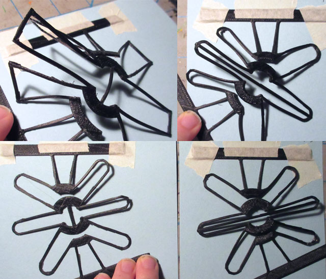
The changes I made to the original mech design was to make the sharp edges rounded. The material seemed to be less stressed this way- less visible white lines from bending.
Designing this for 3d printing- the flexible features were only 1mm in width to make sure that there would be no in-fill pattern. If there was an in-fill, it could change the way the piece flexes.
In the design, there are holes within the flexible features. The idea was to make it more sparse for more flexibility. This would only be possible with additive manufacturing, since a multi-axis cnc mill would be too large to fit between the features to drill the holes.
The tab on the left is borked because I accidentally left Cool on when slicing. Cool sets a minimum time per layer, giving filament time to cool. My printer settings tend to retract too much during cool, and not extrude fast enough when starting again.
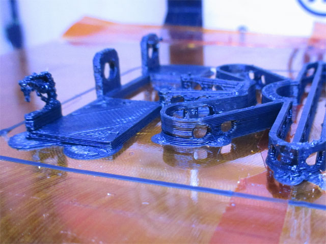
Here were some of the mishaps at 3d printing it:
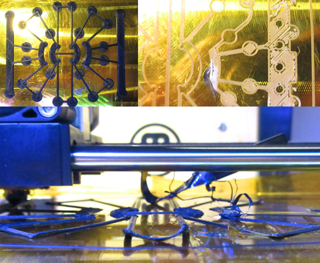
Bottom- The thin features, condition of the build surface (air bubbles, tears) lead to the first layer not adhering properly to the build platform.
Top left- The solution to this problem was to add small 1 layer circles to the corners of the design.
Top right- When switching materials from ABS to TPE, the filament was being extruded slightly anemic. The solution to fixing it was to increase the extruder temp to 230 deg C, and re-level the build platform.
The mech that was printed in TPE (NinjaFlex) was very floppy. It would not be useful in the robot design.
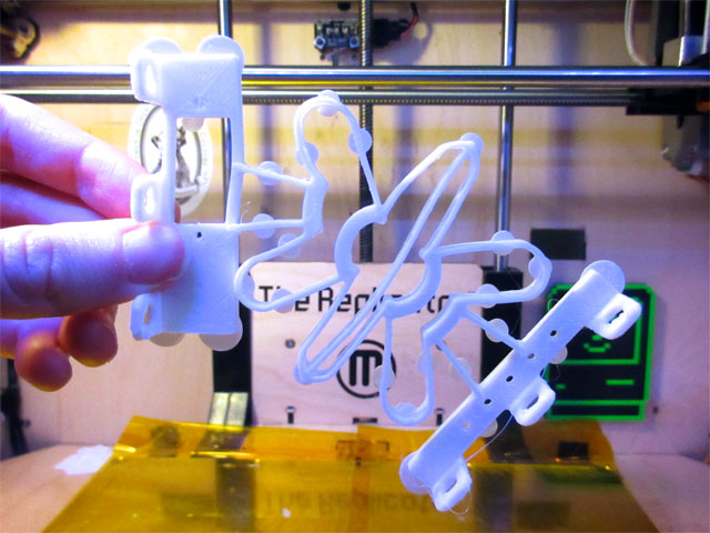
There were some design flaws:
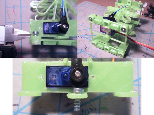
Top left- In order for the screw to not extend past the base ‘spacers’, it needed a washer
Top right- If the screw extended past the base ‘spacers’ then the assembly would be resting on 4 screws. Not as stable. Also the base printed in PLA was too flexible. Should have made it loner.
Bottom- The middle screw did not fit will with the servo in place. Did not need 3 screws per side anyway.
Overall, the mechanism moves too much into the z-axis. It may be because the design I made was not the exact dimensions as theirs. Making the prototype was still useful, as would not have realised this otherwise! I have an idea for a design to try based off of this one that might improve the desired movement.
Post Processing Scan into Antimony

I wanted to be able to display slices of 3d objects in Antimony. The idea was to blend some of the slices together to create interesting combinations.
Ended up not being able to complete the idea, but learned a lot during the process of trying!
Learning about Function Representations
Asked for help on the mailing list about how the functions worked. Thanks to Neil for pointing me in a right direction to learn more about this, and thanks to Troy for the suggestion about Meshlab.
In Matt’s thesis, Chapter 3 is all about functional representations, and Appendix A has info about the math strings too.
It’s complicated information to parse, but I still wanted to try it out.
Warning: It’s possible that all of my info below is completely wrong
I kept getting confused trying to follow the algorithm, because was not sure what the word arguments was referring to. But by using the original tree in figure 3-2 as a guide, it can be figured out.
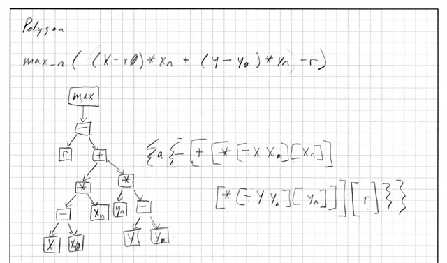
First try was to re-create rectangle corner. Luckily the f-rep expression is in the comments. This plus the string and a vague idea about how the graph works, was able to figure out how the string is formatted.
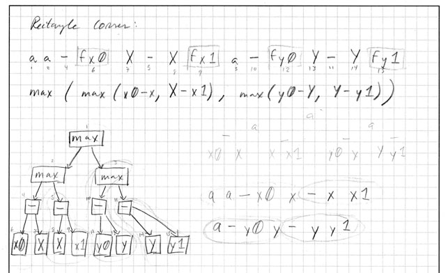
In this first try how I made it work was to just go through the tree starting at the node that has not been recorded yet. It took so long to figure this out...
Then I tried a different way, by recording the very last nodes and grouping it with their operation. This is what the square brackets are for showing. Here it is with Polygon:
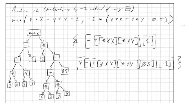
Trying to re-create the annulus from the example graph in Matt’s thesis was difficult. I could never get the -1 to work because there was only one node attached to it. If that makes sense. Not really sure where I was going wrong.
Tried to use a * and then with a -1 and the others, and it worked.
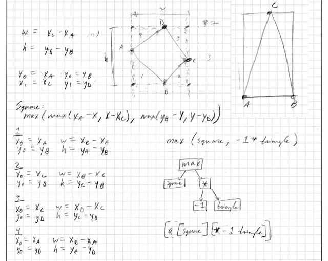
Now it was finally time to dive in to the idea. At first I wanted to create a triangle that fits in a rectangle by subtracting two right triangles from it (right hand side). Then taking this idea further, maybe it could create a diamond by subtracting four right triangles.
To try it out, was playing in Antimony with the right triangle and then noticed that it disappears if the width or height goes negative.
This was my try at fixing it. It did not work at all!!!!!!!
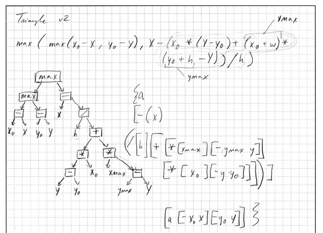
The result were these weird shapes that would move in patterns, and sometimes it would display a hockey stick.
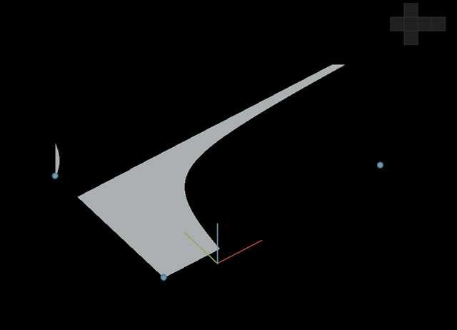
One of the stumbling blocks is that not really sure what all of the max, min, and expressions are all about. Would probably be able to make more shapes if I understood this more. Found this page which might have some helpful info on it -- didn’t see this until Tuesday evening though.
Also only realised to check shapes.py for the triangle function until later. Should have thought of that sooner.
Finding Points
Still wanted to go ahead with the idea even though could not make the triangle shape function work. The next step was to get the xy points from a slice in the model.
Sliced a 3d model of the Stanford Bunny using Autodesk 123D Make. It exports images of each slice as an .eps file. Some of the images contained two slices of the model, so I had to manually edit those.
Created a sketch in Processing to scan the image for pixels that had a red value of < 200. It then recorded the location of the point, and could export the x,y to a text file.
First I tried attaching triangles from two of the points to the centroid. It did not work!
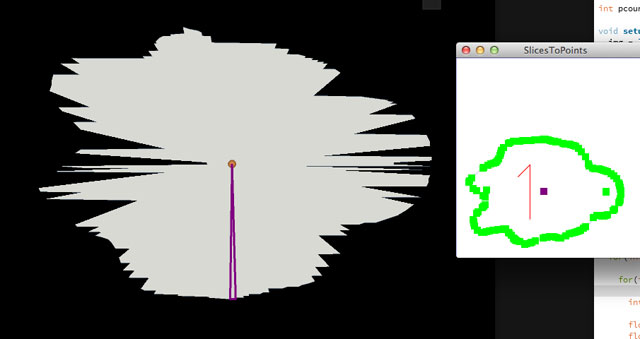
The reason why is because the points were not ordered to be adjacent to each other. They were in order of the scan- which was just going through the image in the x direction and then moving down the y direction.
I tried to redo the program so that it detects the points in error. The cursor would go in one direction, then look at the other directions to see if the pixel was less than the threshold. But it kept running in to the problem where in a tight space it would keep going in the same pattern of movements. I couldn’t figure it out. There are other ways of solving this problem that probably would be better too.
Sometimes there would be a problem that too many points were trying to be displayed in Antimony, it would slow down too much. Added an option in the sketch to skip every so many points in the Processing sketch. This helps with not generating too many points, and you get a similar representation to the outline of the shape.
Reading.node
To display all of the shapes where the points are, I created a node. Here are three of them in action, used to display the pieces of the Fab Lab logo:
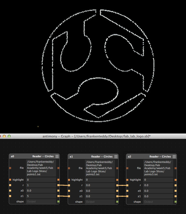
The node has an input for the file path to a text file. This text file contains the x,y points that the Processing sketch generated. The python script then loops through all of the points, and displays the shape.
Originally I wanted to be able to take an input of a shape and use that shape for the points, however I could not make it work. Also, the parameters sometimes vary between shapes.
There’s still some improvements to be made with the script. For example, handling errors if it can’t open the file and also handling the parsing of the text file (may want to include more information at some point).
Result
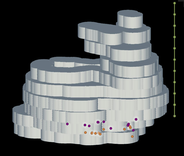
I didn’t realise that the slices from 123D Make were not aligned in any way. So when first processing and displaying them, it resulted a funny looking artifact. After aligning the slices and re-doing it again, it sort of resembles a bunny-
Lessons Learned
- It was challenging and a struggle to learn how the function strings are created. But eventually was able to re-make some of them. Learned a lot from doing this.
- Probably tried to tackle too much for 1 week ... but ended up learning way more than I would have otherwise! Noted that it’s not a sustainable effort level.
- Designing with flexure mechanisms is going to be tricky to constrain the movements in specific axis’
- Decision making process: Usually I start out with what I want to make, try some things, and go from there. It will be useful going forwards if I ask *how* it should happen too. For example, I knew points were needed, but not how they were needed- they needed to be in order for the triangles to work.
Design Files
You can find all of the source files in my repository