WEEK 10 - Input Devices
Assignments: measure something: add a sensor to a microcontroller board that you've designed and read it
DESIGN FILES
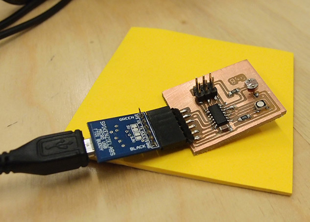
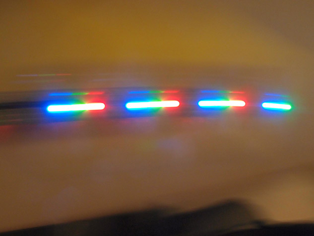
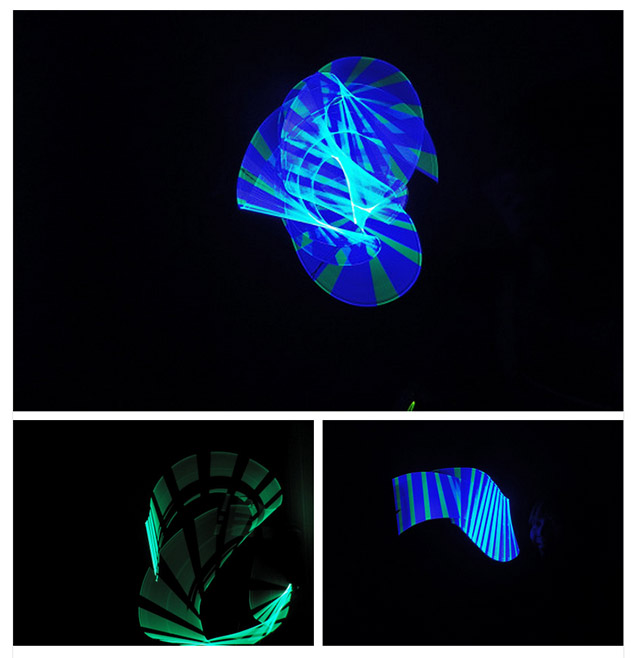
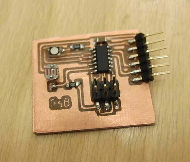
I tought about designing a probe for 3D scanning a surface with a 3D printer for a while. Using processing to send XYZ coordinates to the 3D printer, and reading the Z contact point.. but that was slighlty too complex for this week. So I decided to design and build a color sensor. Blinking every color in an RGB LED and reading the amount of each color bouncing back a surface using a photoresistor. I've messed around a lot with cheap USB flatbed scanners so I could use them as cameras. To do so you first have to disconnect the light source of the CCD without messing with the CCD's data line... quite simple actually, but when you realise that the light source uses 4 wires, RGB led comes to mind. So yeah.. that's how cheap scanners works. blink read, blink read and so on. You can get a lot of fun when you connect it to an arduino though!
So I needed 3 pins for the RGB led and one analog input for the photoresistor... that's all. I don't really mind my attiny running at 8Mhz for this application so I'm running my program without an external clock. And after some testing, 8Mhz is perfectly capable of sending data through serial at 4800 bps.Which is more than enough for this project. So I really went for the simplest design.
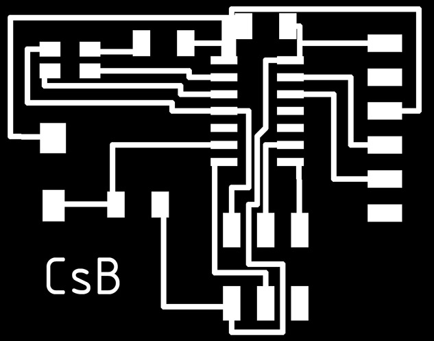
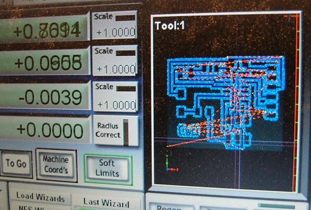
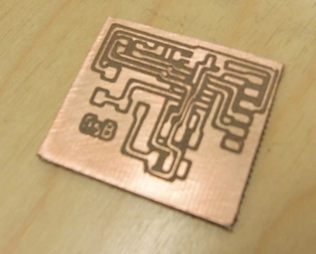
But there was a problem with my design.. I connected one of my RGB led's pin to the reset pin.. I only realized it after the board was milled.. It could easily be fixed as I only did 5 outlines within the fab modules so there was some copper really close that I could cut and bridge. For the milling, I used the fabmodules g-code export.. which should definitely have a pcb milling preset.. not everybody is milling their PCB with a modela.. even though setting is actually pretty easy. I tried to optimize the tool size so I would get only one pass between the closest traces.. just to make sure I'm not tearing off the traces that I need... as this happens a lot.. There should also be an offset distance that you can slowly increase till you find the sweet spot where all your traces are as thick as they can be without having to cheat.. changing the tool size.
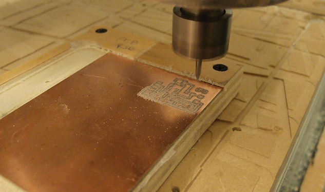
Everytime I mill a PCB, I surface a custom RIG the slightly bigger than my PCB.. everybody's messing with our machine so it's hard to keep it flat for pcb milling.. but it only takes a few minutes with a 1/2" endmill.
Programming in C is like magic to me.. I can't understand anything.. since I know my way with the Arduino IDE, I switched to arduino for programming, adding attiny44 and attiny84 to the list of chips was quite simple.. thanks to the internet.
void setup(), pinMode(), void loop(), digitalWrite(), digitalRead()... easy. the Software Serial library is working fine.. It's probably not optimized for the attiny84, as I can see the available memory going down quite rapidly, but today speed is not a concern I guess. 5 stream of sensor data per second is more than enough for my color sensor board.