Applications and Implications
Overview
My proposed final project is a portable, modular, launch system to be used with
up to level 1 & 2 High Power rockets.
The design of this system is intended to provide a more complete, simple, safe,
and strong solution for the final step of a rocket launch.
Typically, an individual will spend countless hours designing, constructing,
and preparing a rocket for flight. When it is time to launch, many times the
individual will walk out to a pad only to find a primitive tool lacking features waiting for them.
This pad will provide the user with not only the required launch gear, but also
additional accessory items such as pad wind speed and direction, launch angle and
direction, and a protected pad camera mount

1 – High Power Rocketry
 High Power Rocketry, also known as HPR, is similar to model rocketry with differences
that include the propulsion power and weight increase of the model. They use motors in
ranges over “G” power and/or weigh more than laws and regulations allow for unrestricted
model rockets. Like model rockets, High Power rockets are typically made of safer, non-metallic
materials such as cardboard, plastic, and wood, however, construction and recovery techniques
usually differ somewhat, due to the requirements imposed by the use of HPR motors. This means
that these models must be constructed in such a way that they have the ability to safely fly
under these higher stress conditions. - National Association of Rocketry
High Power Rocketry, also known as HPR, is similar to model rocketry with differences
that include the propulsion power and weight increase of the model. They use motors in
ranges over “G” power and/or weigh more than laws and regulations allow for unrestricted
model rockets. Like model rockets, High Power rockets are typically made of safer, non-metallic
materials such as cardboard, plastic, and wood, however, construction and recovery techniques
usually differ somewhat, due to the requirements imposed by the use of HPR motors. This means
that these models must be constructed in such a way that they have the ability to safely fly
under these higher stress conditions. - National Association of Rocketry
Level 1 allows the purchase and use of H and I impulse class motors; solid and hybrid.
Certain F and G motors may also require Level 1 certification for purchase and use. (160-640 n-sec)
Level 2 allows the purchase and use of J, K, and L impulse class motors; solid and hybrid. (640-5120 n-sec)
3 - Materials and Components
The environmental conditions at large rocket launches vary greatly. Some are held on very nice sod farms.
The largest are held in the deserts of Nevada. Most in the Midwest are conducted on farm fields in the off-season.
This tends to mean pads are setup in a rough cut , unlevel field. Many times it is damp and cold.
In Ohio, it is not unusual to launch when snow is present.
This mandates that the material be rugged. Although ideally this project would be constructed from
lightweight steel, this is beyond the scope of a normal fablab. So as to develop a heavy pad, 1/2”
waterproof MDO signboard plywood will be used for the superstructure. All joints will be glued and
bolted if possible. The pad head will be constructed with a combination of signboard and 1/4” laserable
plastic. All tube accessories shall be fabricated from ½” diameter steel electrical conduit.
Various hinges, fasteners, and fittings will be used for assembly. A limited amount of parts will be
purchased including the launch rail and adjustment knobs.
All materials are readily available at local big box stores and my local lumber mill.
4 – Estimate of Probable Cost
| Material |
Estimated Cost |
| Signboard |
$ 35 |
| Hardware |
$ 30 |
| Conduit |
$ 10 |
| Electronics |
$ 20 |
| Plastics |
$ 10 |
| Finishes |
$ 15 |
| Misc |
$ 20 |
5- Parts and Systems


The Launch System consists of four systems.
Superstructure – This will be made to be collapsible. It will be made from signboard cut
on the Shop Bot. Additional finishes will be made on the vinyl cutter.
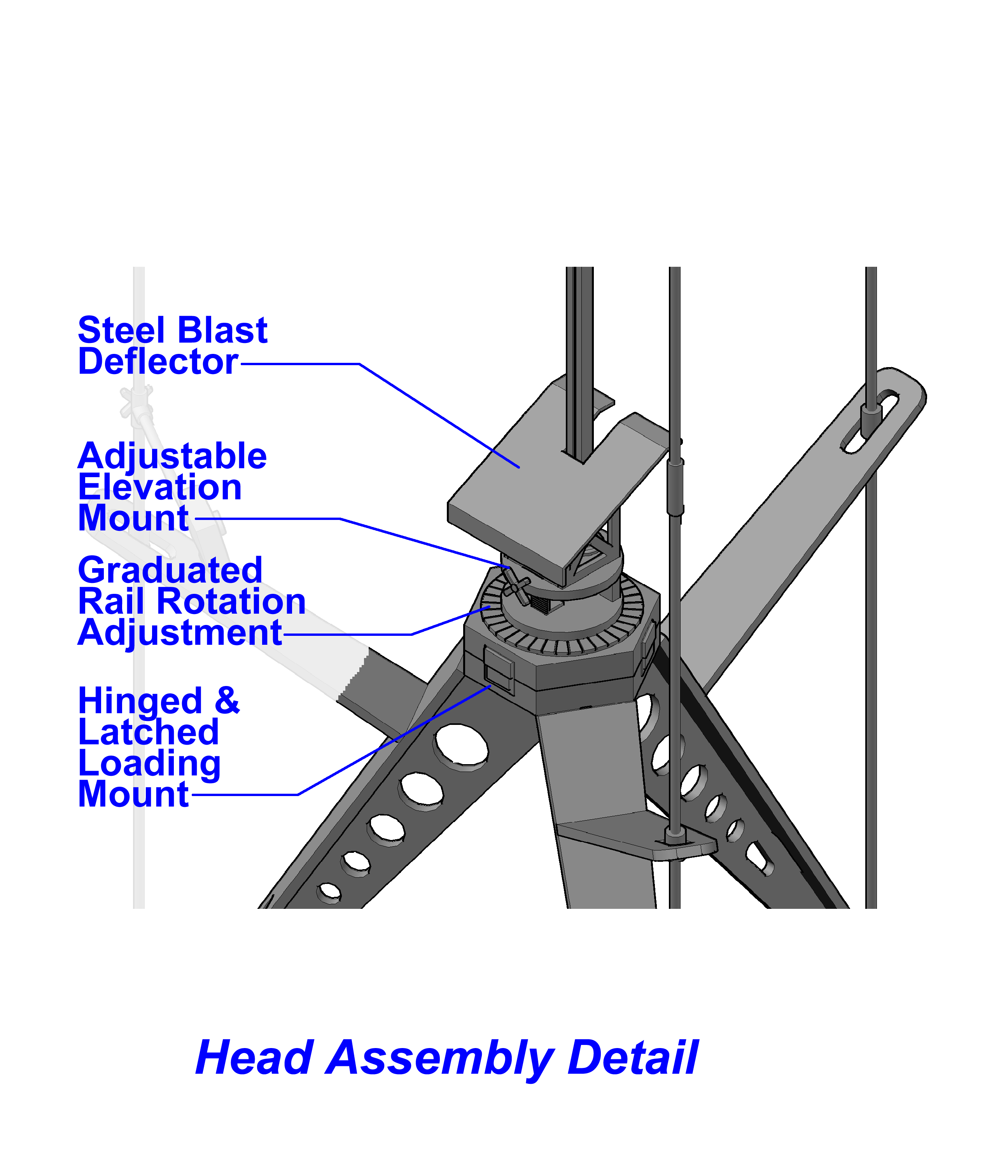
Pad Head – This is made to be hinged for easy loading of rockets. It will be made adjustable
for wind direction and speed. The head will be made from signboard and plastic. Both the
Shop Bot and the laser will be used. The deflector shield will be a build-up of insulated
and non-flammable materials.
Accessory Masts – The primary component of the masts will be cut electrical conduit and
related fittings. The anemometer will be designed and 3D printed. It will spin a motor creating
a current that will be measurable to the launch controller. The windsock will be handmade of nylon.
The camera mount will be adapted as required for the selected camera. An optional launch indication
strobe is also being considered.
Launch Controller - The launch mechanism will consist of a box at the pad holding the electronic and
a heavy duty 12 volt car battery. A circuit board will be designed that will both control a launch
relay and a input/output for the anemometer. Switching and wind speed will be controlled and displayed
from a remote box tethered by Cat5 cable.
6- Employed Processes
| Process |
Task |
| Web Page Development |
All Documentation |
| CADD |
Part Designing |
| Simulation |
Collapse & Transportation Mechanics |
| Large Part Construction |
Superstructure |
| 3D Printing |
Anemometer Construction |
| Electronic Inputs |
Anemometer signal generator |
| Electronic Output |
Signal meter and Launch Strobe |
| Embedded Programming |
Launch Strobe |
| Laser Cutting |
Pad Head |
| Composites |
Blast Deflector |
7- Task Agenda
| Task |
Status |
| Hardware Design |
Completed |
| Hardware Fabrication |
Pending |
| Hardware Assembly |
Pending |
| Electronics Design |
Pending |
| Electronics Fabrication |
Pending |
| Electronics Testing |
Pending |
| Project Testing |
Pending |
8- Project Schedule
| Task |
Date |
| Superstructure Fabrication |
5/20-5/26 |
| Head Fabrication |
5/27 |
| Mast Assembly |
5/28-5/31 |
| Electronics |
5/31-6/5 |
| Project Testing |
6/6 |
| Project Presentation |
6/10 |
9- Anticipated Issues
 - Is the Launch Pad and Accessories easily transportable?
- Will the anemometer and masts be useful and accurate?
- What s the durability of the signboard?
10- Project Evaluation
 The project will simply be judge on its performance and appearance. Is it easy
to setup, use, and tear down? Does your rocket look good launching from it? Are
the accessories helpful? Did the system increase your enjoyment of the hobby?
The project will simply be judge on its performance and appearance. Is it easy
to setup, use, and tear down? Does your rocket look good launching from it? Are
the accessories helpful? Did the system increase your enjoyment of the hobby?


