About me
Final project -
development
Final project
Weekly projects
Wk 8 Large Format
Machining (Mar 18)
Assignment:
• Make something big
Design
Last week,
a dear friend of mine asked me "So
what's your project this week Sal?!". When I told
her the brief was captured in three words "make
something big", she said "Any chance of a
new garden bird table?" I
thought it was a nice challenge.
I had witnessed many times, magpies and crows swooping and
stealing bird feed from the
smaller more vulnerable
garden birds on her bird
table and so I wanted my
design
to offer
some element of
protection for them.
Something that would
enable them to move
freely (due their
size) and
make
swooping
difficult for
the larger
birds, whilst
not prohibiting
the view from
the house
window.
After
an initial idea
and sketch,
I set about
cutting some
cardboard by
hand so that I
could see the
form as soon
as possible in
space.
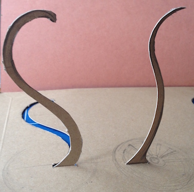
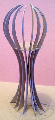
I
then set about
tracing the
cardboard rib
as a vector
drawing in
Affinity
Designer:
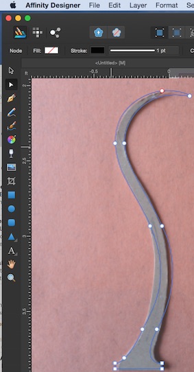
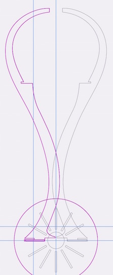
I tried to draw
the vector paths in both Affinity Designer (£39) and
Inkscape (free). As I am new to both applications, a
large part of the week was trying to create these paths
and refining design and structural detail as I went
along. Given my design was quite tall with minimal in
structural support, my tutor pointed out that a lock
joint would help to give strength.
Affinity has some very powerful and sophisticated tools
for recognising geometrical relationships and snap-to
tools. Moving to Inkscape after Affinity feels like a
downgrade, then again, Inkscape is free.
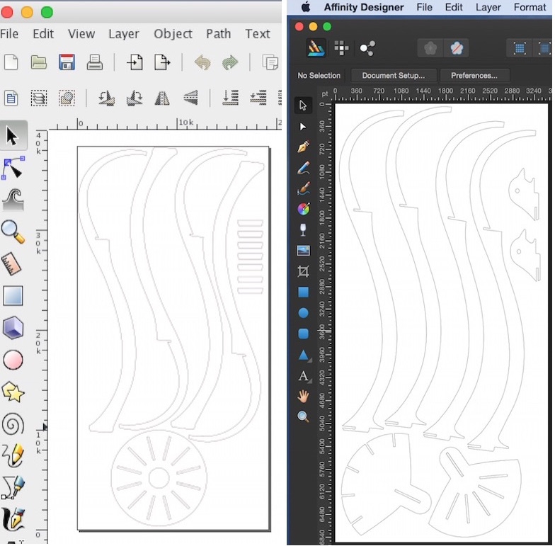
If I had more
fluidity in 3D CAD I would have definitely tried to
progress further using Rhino than I managed to do.
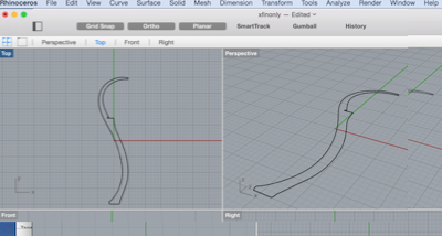
A 3D model of the design in space would certainly help
me identify any potential design flaws. I imported the
rib into Rhino to see the structure in space and
be able to more easily slice and select 'planes'
for intersecting pieces, but in the time available
I was not able to progress quickly enough, so
I focussed on preparing the form in 2D to create a pdf
for the Shopbot Milling Machine.
HEALTH and SAFETY
Health and Safety is the most important aspect of
working with the Shopbot machine. The tool itself is
surprisingly unguarded and moves across X Y Z axis, so
its critical to be mindful at all times.
When handling materials, gloves should be worn
to protect from splintering. Goggles must be
worn to protect eyes from the possibility of loose
pieces flying off the bed, or worse, the tool itself
shattering. The milling action creates a deafening
noise compounded by an extractor fan, so ear
defenders are also must. Although we do have an
extraction fan in the lab, I could feel the irritation
of the dust particles so I also chose to wear a mask.
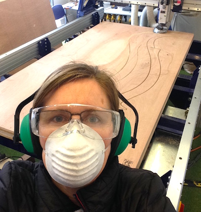 I am under there
somewhere.
Setting up
and preparation for Milling
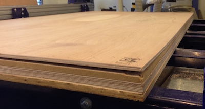
The material I had chosen to
work with was 12mm ply. In actual fact the material
varied between 11.0 and 11.4 and this had to be
accounted for in the dimensions of all joints; an
average of 11.2mm was applied. The Computer
Numerically Controlled (CNC) Machine that we had at
our lab was a ShopBot machine. The software used to
create the toolpaths was Partworks.
Once the material was placed on the bed, it became
apparent that one corner of the piece was slighlty
warped. This made clear the importance of laying the
material as flat and sound to the bed as possible, so
7 points were chosen to screw the material solidly to
the bed. I had to refer to the layout of the design to
ascertain where to best place the screws - ie, in the
waste sections and where they would be most effective,
considering any weak areas and those prone to
vibration.
The machine was now ready to have the X, Y and Z
axis 'zeroed' (- the origin offset is never used in
Partworks) .
The machine was powered on and the tool column could
now be moved by left-right on the PC keyboard to bring
the middle of the tool bit to the origin of the bed /
material. Finding the X and Y axis is straight forward
and done by eye alignment along the length of the
material.
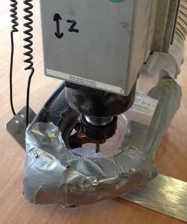
To determine an accurate zero for the Z axis and to
avoid damaging the material (which is soft relative to
the powered drill bit), the Z axis zero origin is
detemined by use of a metal plate of a certain depth
(known and previously calibrated in Partworks), which
is placed solidly on the material (away from the
edges) and under the drill bit (choose a clean
undamaged area). A metal clip is attached onto drill -
this establishes an open electrical circuit. Upon
selection of Z-zero on the PC control panel, the tool
tip automatically travels down and detects the right
contact with the metal plate (closing the electrical
circuit - check for green light in the control panel).
This process completes the Z-zeroing
Checking and amending the toolpath in PartWorks
(ready to mill)
Partworks (the software
that controls the shopbot) is where final checks
and refinements are made to the pathwork before
calcualting the final toolpaths to mill.
Dog and T-Bone fillets
Most joints are square in form. However a milling
tool is circular. The
'Dog-Bone' and 'T-Bone' fillets allow
toolpaths to mill into corners of slots and
grooves, allowing mating parts to fit flush.
This also allows the limiting radius of the
cutter to be removed from the bottom of slots.
This ensures the strongest possible engagment and
fit. Choice depends on the
needs of the design and whether the joint
can be visible or needs to be hidden for
aesthetic reasons.
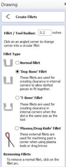
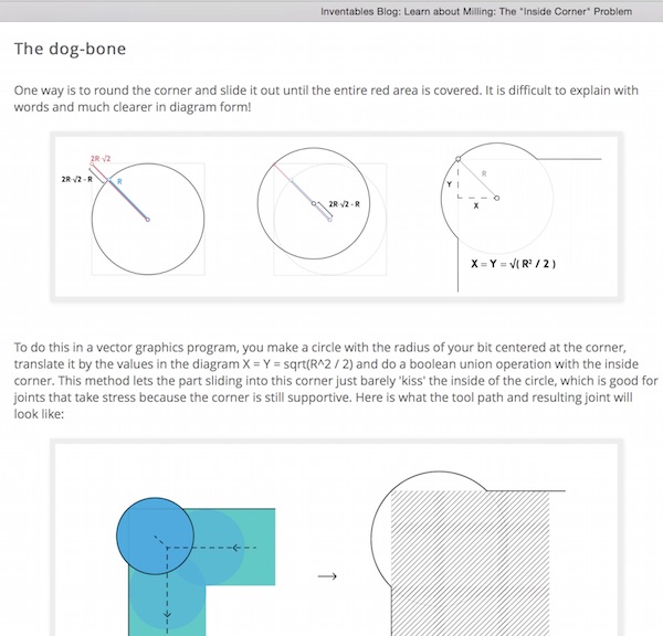
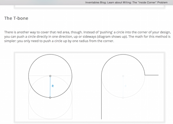
When I transferred my pdf file to
Partworks, all the vector lines were closed as
required, which is good. However there was quite a bit
of work to do. For example,
we found duplicate line work which needed to be
deleted. Also, in some places, the click-on-path
feature in PartWorks to assign a dogbone fillet in
a corner would not work in every position. In some
places, new traces had to be drawn over existing
lines and then the fillets would work. In some
cases, by reducing the radius of the cutter in the
dogbone settings, the fillet would also work, as
the software would not allow the fillet to extend
beyond the width of the slot.
In future I would choose to go through
this process outside the shopbot PC environment to
make sure it was truly ready to mill.
Toolpath set up
There are 3 toolpaths to choose from. Profile,
Pocket (for scooping out) and Drilling.
I chose 'Profile' toolpath; outside; climb. Tool was
going to be 6mm downcutting tool, which would give the
best finish in this set up. Settings are cpatured in
screen grab below:
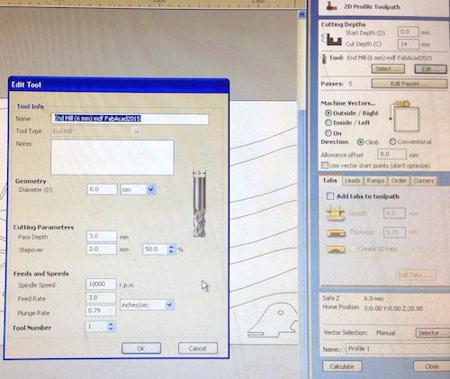
Depth of cut passes were edited, taking
into account the depth of the material, and the amount
of passes calculated by Partworks. This is optimised so
that the best finish is obtained on the last pass of the
mill, ie it gives best result when the tool has
around 50% of its pass in the material to be cut and 50%
of the tool passing through the sacrificial layer.
This helps to avoid tearing on the last pass.
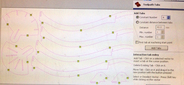
Adding tabs
In order to keep the material being cut to remain
stable and safe under the power of a 18,000rpm end mill,
tabs are added to the toolpath. The terminology is
misleading, because, in fact the reverse is happening;
'adding a tab' means that the end mill toolpath skips a
few layers (around 4mm sq area) in the toolpath, leaving
a link to the main body of the material so that it does
not fly off.
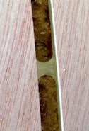 Example of a tab
Tabs can be placed evenly distributed around the pieces
being cut, and in particular where there may be
increased weakeness, risk to fly off or potential
tendency to vibrate and cause damage to the finish.
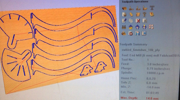
Toolpath summary:
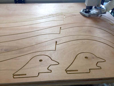
Mill cutting the plywood
I was very happy
with the quality of the cutting, it was clean and
sharp.
However there was still an hours worth of sanding to
do around all the freshly cut edges.
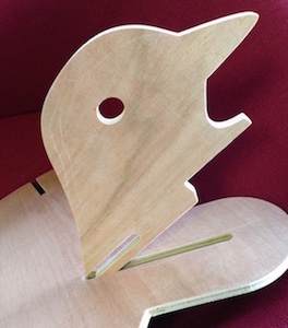
The photo above
shows the detail of the locking joint used, that would
give further strength to the design, as well as
clearance from the ground. The bottom edge
of this piece would provide a third foot to lift the
table off the ground (as three contact points gives
the greatest stability). Before, leaving the
lab, I tested the joints to ensure that the tolerances
of the assembly were workable. There was good firm and
solid engagment in the clearance between the pieces.
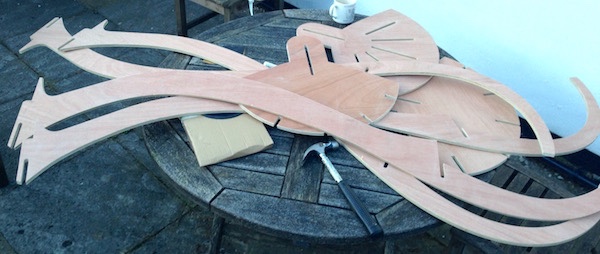
However,
as I did not want to put any unneccesary stress or
torsion on the structure (in transit in my car), I took
the flat pack, carefully protected and packed, to my
friends garden to assemble in situ.
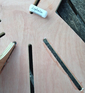
To help ease the joints together, I used grease
in the form of lipbalm smeared on the edges. This
definitely helped the assembly push-fitting process
and reduced the stresses so that any fragile joints
could be protected from fracture.
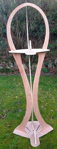
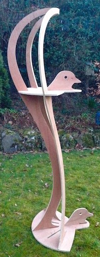
View 360 degree movie here
Download design file here


I am under there somewhere.

Example of a tab


