About me
Final project -
development
Final project
Weekly projects
Wk 6 Electronics
Design (Mar 4)
Assignment:
• redraw the echo
hello-world board, add (at least) a button and LED
(with current-limiting resistor)
• check the design rules, and make it
• extra credit: simulate its operation
Resources
and useful guides
Good tutorial on this week's
assignment can be found on the 2015 archive - click
here
Assignment:
Redraw the 'Echo Hello-world' Printed Circuit
Board
Introduction
As a beginner in this field, I oriented myself to the
assignment ahead by reading through the relevant links
above. Most of the learning this week was within Eagle
(Easily
Applicable Graphical Layout Editor), which
is a Printed Circuit Board (PCB) Design Software which
provides a schematic editor, layout editor &
autorouter, all within a single interface.
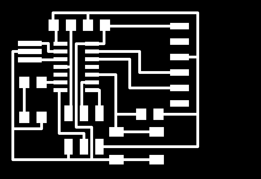
After downloading and installing all relevant software
and files I opened BOTH the schematic
(.sch) and the board (.brd) files. As Eagle
updates changes made on one file in real time to the
other, both must be open as you begin. The image below
shows how the files look when first opened, with some
parts already in place on the schematic (left)
and consequently also on the board (right):

The complete component list that we were following was
as follows:

Everything was going fine until I remembered that I
had seen a grid underlay on one of the
tutorials and thought that it could be a useful 'snap
to' support. I went about finding and turning on the
grid. I changed the grid unit to a nice rounded metric
number. Now, I started adding all the components from
the relevant libraries in turn.

HOWEVER
If you look closely, you will
notice, that the switch button that I added in the top
right hand of the image above - "S1BUTTON" - did not
snap to the grid as had all the other parts already
placed (on opening). As explained below:

Therefore I
had to delete all newly added parts, change the units
back to the default settings and re-add all the
necessary parts from the libraries. This fixed the
alignment problem - see scematic below. SO DO NOT
CHANGE GRID UNITS!

Frequently
used technical terms
Airwire:
Unrouted connection on a board, displayed as thin
yellow line in the unrouted layer (= rubber band).
Design Rule Check (DRC):
EAGLE can identify the violation of certain Design
Rules (e.g. if two different tracks overlap or are
too close) with the DRC.
Electrical Rule Check (ERC):
EAGLE can identify the violation of certain
electrical rules (e.g. if two outputs are connected)
with the ERC. It also checks the consistency of the
schematic and the layout.
Forward&Back Annotation:
Transforms all the actions one makes in a schematic
online into the lay- out (and with limitations from
layout into schematic). Both files are consistent
all the time.
Net:
Electrical connection in a schematic.
Pad:
Through-hole pad associated with a package.
Pin:
Connection point on a schematic symbol.
Ratsnest:
Command for calculating the shortest airwires.
Signal:
Electrical connection in a board.
Supply Symbol:
Represents a supply signal in the schematic. Causes
the ERC to run special checks.
Symbol:
Schematic representation of a component, stored in a
library.
Wire:
Electrical connection in a board, or a line (since
lines are drawn with the WIRE command).
Now, with schematic completed, I could check
the board for errors using the Error tool - see below.
 (ERC =
Electrical Rule Check; DRC = Design Rule Check;
Errors).
(ERC =
Electrical Rule Check; DRC = Design Rule Check;
Errors).
Some 'warnings' were shown but seeing as some of the
pins were not being utilised, I decided that these
were not problematic at this stage and proceeded.

I also had a look over the Design rules and left them
in their default settings to see how they would appear
on the board.
I could now switch view to work on routing the
board, on the accompanying file.
On 'switching' to view the .brd file, all the added
components get 'dumped' in a jumble in the left hand
corner - this is normal.

Also illustrated in the image above are the 'airwires'
- the unrouted connections - in thin yellow lines.
These are what Eagle displays as a guide for routing
the correct connections on the board (drawn as the
red graphic lines) based on the connections
I made in the schematic. At any time, if further
changes are required, by switching back to the
schematic, it is always possible to edit. I was
beginning to like Eagle.
I could now go about moving all the added parts into
the most efficient layout without compromising clarity
and precision of traces and connections (with support
of sample in tutorial).
When I first went to place all my added parts into
position, I noticed that I had used too much
descriptive text, which cluttered the board, therefore
I went back to edit the text in the schematic - shown
below.

It's a very satisfying feature to follow the airwires
to route the board, at least on this relativley easy
board:

Design Errors
Again, by using the error tool, some errors were
revealed as cross-hatched areas, as shown below:

I had routed across the resistor, and there was an
errant airwire showing up a faulty route. Both were
deleted and re-routed.
Here are some common errors to look out for:

I was now ready to switching off the layers
(text, etc) on the board view to export a .png file.

This was
edited in Gimp to expand the boundary by 20 pixels
on each side to provide a good working boundary on
the PCB.

The file was duplicated in Gimp to produce a cut
out file for the Modela milling machine.
Here's a reminder of the workflow on the Modela
using the fab modules;

During the second milling of my board to cut it
out, there was a clear 'something
is not quite right' sound. I
interrupted the milling by pressing standby. The
mill had cut right through the middle of my board.
On closer inspection, it became clear that I had
omitted to tighten the second grub screw on the
collar. The end mill bit had not been damaged, but
the board was irrecoverable - see below.

My second attempt, with both grub screws secured
on the collar, the board was milled successfully -
see below. However, this shows quite a lot of
burring around edge of each trace. This required
much more work to deburr and clean than the last
time I used the Modela 2 weeks ago, illustrating
the slow demise of the end mill. I used a ruler
edge and very fine sanding paper to deburr and
clean the board. See the cleaned up examples
further below.

Once deburred and cleaned, it was time to return
to the soldering station.
With poor eyesight, I need to make sure that I
orient components correctly. On the ATTiny
microchips there is a tiny dimple on in the black
plastic in one of the corner which reveals the
position of pin 1 - see below. Also shown below is
the anchor solder ready to recieve the resonator.

The board required an FTDI connector. This enables
connection to an FTDI cable which is a USB to
Serial (TTL level) converter which allows for a
simple way to connect TTL interface devices to
USB. This will provide a power supply to the PCB.
The FTDI connector that fab lab use, given we are
using surface mounted components, mean that the
connector had to be soldered at an angle. Once I'd
soldered an anchor in the middle of the
pads, I found it helpful to use blutack to
stabilise the component at an angle whilst I
melted the anchor solder - see below.


Soldering complete:

Testing the board and simulating its operation
- a success.
Its a bit subtle in the photo below, but trust me
when I say, "my board is blinking!" and so am I.
Happy days.
Note: the 6pin rainbow connector is connected
'away' from one chip and 'over' the other on the
other board. This is a significant configuration
and needs to be consistent, although it's possible
to do vice versa also, but not the same on both
boards. (I will try and find a way of making that
clearer in future weeks).

Download Eagle Schematic
Download Eagle Board
SWHelloEchotraces.png
SWHelloEchointerior.png
