About me
Final project -
development
Final project
Weekly projects
Wk4 Electronics
Production (Feb 18)
Note:
Assignment for Week 4 is to make a
programmable micro-controller - also known as a
FAB ISP.
Tuned in to regional reviews to
learn from others process and development. This was
followed in the afternoon with Neil
Greshenfeld's introduction to Electronic
Production.
Assignment:
Making a
programmer
For
Fab Lab tutorial, click
here.
Preparation of board and sacrificial
layer
In order to get the best result (a board
milled through the copper to a consistent
degree), it is critical that the board is placed
upon a very clean surface with NO undulations
that could change the depth of milling as the
bit traces it's path. The board to be milled is
placed on a 'sacrificial layer'. (At Fab Lab
Manchester, this was a larger copper plated
board used for its engineered precision). There
was some residue of adhesive tape on this layer,
and therefore this had to be thoroughly cleaned
and brushed off with white spirit and cloth.
The board is adhered to the sacrificial layer
with strips of double sided tape (pressed firmly
down). It was important that no bubbles get
trapped under the tape, and also that the tape
strips were close together so that the firmest
adhesion was made to the sacrificial layer.
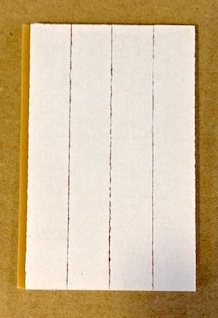
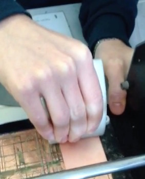
Pressing sticky backed copper plate firmly onto
bed at 0-0 position of sacrficial layer
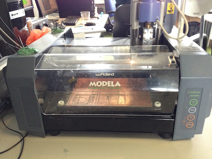 Roland Modela Milling Machine
Milling
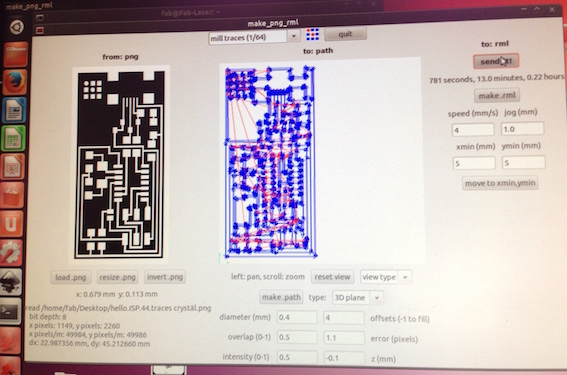
The image below shows the trace file (hello.ISP.44.cad.)
loaded
into the control panel of computer terminal (Click
here for link to files). I was using the
mill trace defaults setttings for the Modela.
This used the 1/64" end mill bit.
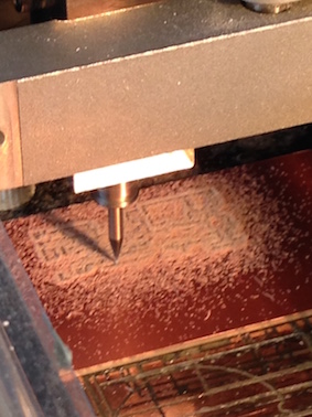
The
end mill had to be zeroed on the x,y
and z axis of the copper plate, then
the x and y axis was given a 5 mm
clearance of corner edge as a start
position. It
is important that the end mill bit, mills
clearly through the copper plate layer of the
board to remove any possibility of connectivity
being made where it shouldn't.
Once the trace path was milled successfully, the
'cut out trace' path was loaded in the control
panel. This would cut out the boundary of
the board
from the rest of the copper plate
stock to
it's working size. The end mill bit used for
cutting out on the Modela was 1/32"
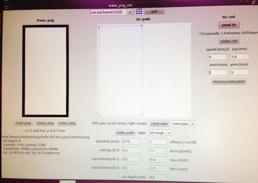 Cut out trace
path
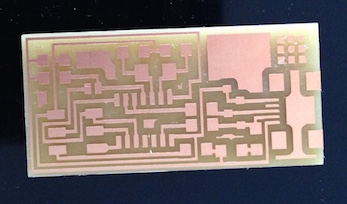 Milled and cut out board
The board was deburred (from any splices of
copper around the edging, and from any unclean
milling). The board was then washed with a
sponge to clean and degrease (from natural oils
on fingers)
Soldering
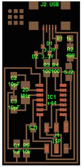
Following the schematic drawing to solder all
the components onto the board. I enjoyed this
process, although a magniying glass was
critical!
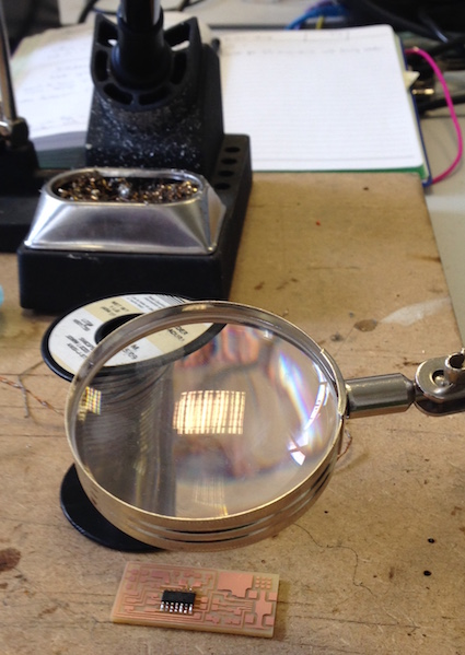
At the soldering station with my crown jewels,
with
soldering iron (300 - 350 degrees),
solder reel, tweezers,
copper cleaning braid tray, magnifier and
extracting fan at hand. The copper cleaning
braid and solder sucker were there in case it
was necessary to remove solder when errors were
made.
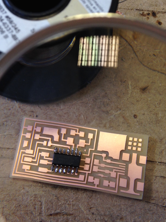
Just a little but proud at this point! (that's
why the image is a little on the large size).
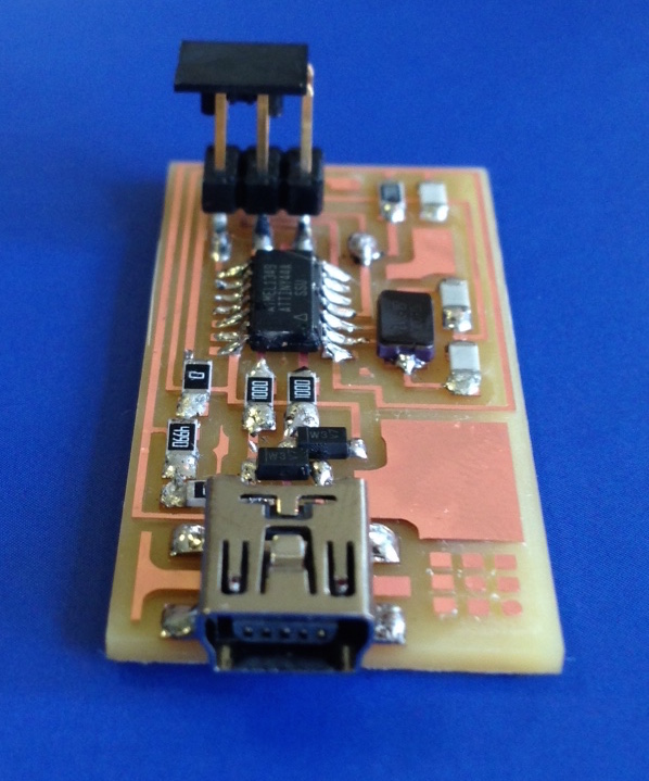 Fab ISP
I tested some of the connections with a multi
meter. The multimeter will show whether there is
a voltage being picked up between two points.
The multimeter proved the board to be clear of
any shorting faults and ready for the smoke test
and then programming.
For this sequence I successfully followed the
'smoke test' on the tutorial here
- plugging the FabISP into my laptop via the
mini USB cable. I did NOT get an error message
on my computer 'drawing too much power' so this
further supported that the board was clear of
any 'short circuiting'. Quite a relief.
I downloaded Crosspack and Xcode to enable the
programming of the microcontroller. I then
followed the tutorial here
to
program the board.
The board was programmed succesfully!
Once
programmed, the 0 ohm resistor and solder bridge
were removed with the use of the solder removing
tool.
The board is now ready for use over the
following weeks at Fab Lab.


Roland Modela Milling Machine

Cut out trace path
Milled and cut out board

Fab ISP