About me
Final project -
development
Final project
Weekly projects
Wk 11 Output Devices
(Apr 15)
Assignment:
• Add an output
device to a microcontroller board you've designed
and program it to do something
Background
I
wanted to use
Output
Device week to
make a useful
contribution
towards my
final project.
In essence I
was developing
a wrist
wearable
digital mala
for recording
and training
the mind in
mindfulness.
This concept
could include
a secondary
device which
would be place
in the home.
This wrist
wearable would
connect
with the
secondary device
which would
interpret and
express some of
the
accomplishment
of time recorded
as mindful
during the day.
There are
three
ways I
wanted to translate
this
information:
1
light
2
rotation
of prayerwheel
(prayerwheels
are
traditional
Buddhist
sacerd objects
which can
contain 1000s
of sacred
mantras; as
the prayer
wheel is rotated
- traditionally
spun on a
spindle by
hand,
the
auspiciousness
of the prayers
are said to be
caught
and carried by
the elements.
3
statistics to
demonstrate
progress
in graphs
So,
here, in
Output Device
week, I would
use a DC H-Bridge
Motor Driver
on my board to
enable
and simulate
the rotation
of a
prayerwheel. I
used the
'hello.H-bridge.44'
board as a
basis.
For the
purpose of testing,
I added
2 buttons to
enable me to
rotate the
motor both
clockwise and
anti-clockwise
(although a
prayer wheel
only rotates
clockwise).
Configuring
the Schematic
in Eagle
The
first part of
the weeks'
assignment
was taken up
by trying to
find the
components in
the Eagle
libraries. One
of the items
cited
on the
hello.H-bridge.44
board
is "IC3
A4953".
I
went on
a wildgoose
chase trying
to find this
part.
It was
not listed in
any
of the Eagle
libraries that
I had
downloaded
from the
earlier electronics
weeks,
including
the
ng
library and
the
fab.lbr.
Although I
understand
that I could
have substituted
with
another
part
with same
footprint,
as beginner I
did
not have
conviction
over making
the right
choice.
Thankfully,
I
received another
fab.lbr
database from
a
global peer,
where the
part was
listed as
an
unique
part with its
specific footprint.
I could now
proceed
to
complete
configuring
the schematic
with
confidence
that I was on
track again.

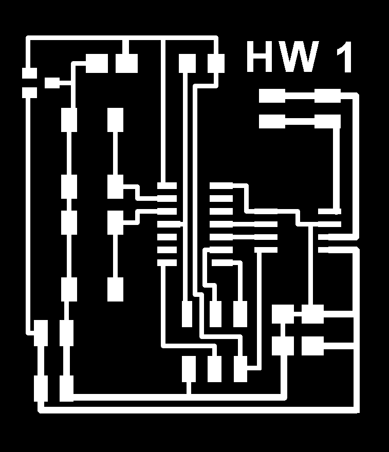
Board with
airwires ready
to plan:

Routed
board:

Correcting
routes
in Gimp:
In
some places
on the board,
the routes
looked too
close to footprints
and some
additional
routes needed
thickening to
take
into
account an
increase in
power
supply. I made
these
alterations
in Gimp with
the drawing
tools.

Corrected
file :

The
board was extended
by 40 pixels
on both x and
y axis and
'trace' and
'interior'
versions
were saved ready
for milling.
Milled
board:

Stuffed
board ready to
test:

Initial
continuity
tests showed
shorting-circuiting
on
the board
After
revisiting the
board in
Eagle, a
connection was
spotted bridging
the capacitor.
I realised
that I had forgotten
to run
a design rule
check, which
would have
shown this
error:

As
this was
easily fixable
on the board
itself,
I desoldered
the capacitor,
removed
the copper
layer on the board
by blade, and
then bridged a
tinned copper
wire
section to
create the
right route:

Once
this correction
had been made,
the board made
all the right
nosies under
the
mulitmeter. From
the terminal
window,
changed
directory to
inside this
new folder and
then ran the
'make program-usbtiny'
command which
showed
to be 100%
succesful.
As
soon as this
was done, when
the power
supply was
connected, the
motor ran its
sequence of
varying
rotations and
rhythms
from
"hello.H-bridge.44.DC.c".
See
green blurr
below:

Modifying
the sample
code
Using
NG code as a
basis, and
with the help
of a tutor,
I was able
to amend
the code so
that the 2
buttons could
be used to
rotate the
motor. "Button
L", whilst
being pressed,
would rotate
motor
clockwise;
and conversely "Button
R", whilst
being pressed,
would rotate
in reverse the
direction. It
was noted that
the motor
struggled to
turn with the
delay set at
5µs; this was
changed to 3µs
and worked
succesffully
both ways.

Download
files:
hello.H-wheel.44.DC.c
makefile2
(After
downloading makefile2, you must rename
as "makefile", removing the "2"). (This
is because the command instructions for C
programming are taken from a "makefile".
As I have more than one makefile in my
webfolder, I chose to name them
"makefile1", etc.
HelloWheeltraces
HelloWheelinterior
Eagle file - schematic
- board
