About me
Final project -
development
Final project
Weekly projects
Wk 10 Input Devices
(Apr 8)
Assignment:
• Measure
something: add a sensor to a microcontroller board
that you've designed, and read it
Background
Starting
week 10 on
input devices
quickly
revealed to me
that I did not
have
sufficient
knowledge and
understanding
of electronics
to progress
quickly.
Without a more
basic
foundation in
the principles
of connecting
components and
direct guidance
on routing the
board in
Eagle, I ended
up wasting a
lot of time
unnecessarily
this week.
I had wanted
to use Input
Device week to
make a useful
contribution
towards my
final project.
In essence I
was developing
a wrist
wearable
digital mala
for recording
and training
the mind in
mindfulness.
In some
buddhist
traditions,
there are
certain
practices
which need to
be accumulated
(up to a
specific
number - which
reflects the
amount of
practice one
has
accomplished).
Therefore, I
want to
integrate an
additional
feature on the
wrist
wearable
- a
semi-automatic
and
intelligent
means to count
(‘hinder-free’),
accumulations
of yoga
postures (such
as Sun
Salutations or
Prostrations
for example).
So, here, the
use of the
phototransistor
becomes very
useful; when a
single yoga
sequence is
completed, the
body lies flat
to the ground
with arms
extended over
one’s head,
flat on the
floor. With
the
phototransistor
embedded
within the
inside of the
wrist
wearable, when
the wrist
makes that
contact with
the floor, the
light is
blocked. When
this event
occurs, the
LED would
confirm a
single count,
and the code
would count 1.
As this action
is repeated,
the yoga
postures being
accumulated
are
automatically
and
effortlessly
counted and
recorded.
Plan
A
Therefore,
I wanted my
board to
include the
following:
1 - use a
slide switch
to enable and
control a
specific
function
relating to
the
phototransistor,
for a
switched-on
period of time
(to disable
accidental
counting
whilst
blocking the
light);
2 - use a
phototransistor
as a means to
measure when
the light is
blocked (the
wrist wearable
has made
contact with
ground and
light
collection is
disabled;
reflecting a
single
sequence of
yoga movement
is completed);
3 - an LED
confirms that
the
phototransistor
has recognised
the event and
a single count
has been
recorded.
4 - an
additional
button to
enable
counting
moments in
mindfulness
training.
Therefore, the
board that I
tried to
create in
Eagle
(schematic),
included a
phototransistor,
a button, an
LED and a
sliding
switch, using
ATTiny 44.

However, when
it came to routing
the
board feature,
I could
not get it to
a workable
configuration.
I tried
auto-routing
and manual
routing (for
days!). I also
had
configuration
errors which
even Eagle
couldn't tell
me
about.
So it was back
to the drawing
board to a
simplified
version. I
also needed
more guidance
to progress.
Plan B
The most
important
feature that i
required on my
board was the
phototransistor;
the sliding
switch could
be simulated
by the
conection and
disconnection
of the usb;
and I could
worry about
the button
later on. This
simplification
meant I could
downsize
to the ATTiny
45.
Pin
out for
ATTiny45:

Components
added in
Eagle Schematic
View showing
simplified
board
using the phototransistor
and LED:

Components
ready to be
configured
in Eagle
Board View:

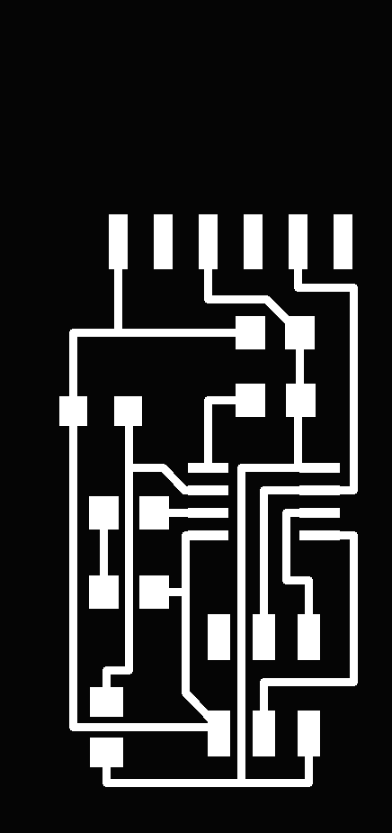
Board
routed
successfully (finally)
:

Components soldered
onto board
The
board was
milled
succesfully
and then the
components
were soldered
into place.

I
inspected the
board, and all
connections
looked good to
me. Wherever I
had a doubt
(slighlty dull
solder),
I
returned to
re-solder.
I conneted the
FTDI connector
to power
up the board
(from the
laptop) and the Fab
ISP to program
the board.
Having
selected all
the relevant
parameters
(Board -
ATTiny;
Clock -
8MHz
internal;
Processor -
ATTiny45;
Programmer -
USBTiny
ISP), I
proceeded to
burn
the
bootloader.
An error
appeared : "Programme
operation not
supported.
Error
while burning
bootloader".
I
could discount
the peripheral
boards as
these were
in
100% working
order (from
previous
assignements)
and were
recognised
without error
by the laptop:

The
board was now
checked thoroughly
with use of a
digital
multimeter,
and with the help
of a tutor.

There
was one
connection
that did
not display a
100% solid
connection.
I re-soldered
and tried
burning bootloader
again. The
same error
appeared repeatedly.
I
also
downloaded
Python and ran
the command to
"flash" the
bootloader,
but it
ran the same
errors.

This
was
unfortunate as
it
meant that I
could yet
proceed to
test the
measurement of
light into the
phototransistor.
I had compiled
my code ready
in Arduino and
had
managed to
successfully
interpret
and correct
all the
errors.
Shown
below is the
code to
measure and
count the yoga
posture
sequences
by use of the
phototransistor:

Milling and
soldering a
new board
Having
checked for
possible
errors
on the board, it
was possible
that my Attiny
processor
either faulty
or overheated
(in
soldering -
although
there was no
yellowing on
the board to
indicate this),
therefore
I made a new
board.
For speed,
I decided
not to try
and redesign
the board in
Eagle;
I would use a
physical
bridge over
the Attiny.
New board:

Connecting
the board:

Programming
the board:
Dowloaded
NG .c code and
makefile
(placing and
renaming
makefile
in dedicated
folder on
desktop). In
terminal
window,
changed
directory
('cd' into the
folder) and
then
ran the
program with
'make
program-usbtiny'.
For
the first time,
the new board
flashed
successfully.
Additions
and modifications
to the
code
With
the help of my
mentor,
the
following
parts of the
code
were
added to
NG code:
•
led pin
definitions;
•
set threshold
on the
phototransistor
for the led light
to come on;
For
my own record,
I have
extracted and
included below,
aspects
of the code
that was added
or
modified:

The
board worked
successfully...
when the
phototransistor
was close
to being covered,
this
would be
recognised and
the led would
confirm this,
as shown below:


It
was noted that
the
phototranistor
was very
sensitive to
any changes to
the
ambient light
in the room.
This would
make it harder
to establish a
reliable
light-to-darkness
change
range with my
final project
device.
When I
repeated the
test at home,
the
phototransistor
was even more
sensitive, as
there was
a flood of
light from a
near window.
I experimented
with pushing
blutack
around
the PT
to block
ambient light.
Once
the body of
the PT was
encased in this
opaque
material the
results were
much more stable
(without any
oscillations)
and
repeatable:


I
also ran the
Python program
via the
terminal window
(using "python
hello.light.45.py
/dev/tty.usbserial-FTHHQE77")
and this
provided a
visual display
of the varying
states of the
phototransistor,
shown below:


Download
Eagle schematic
here
Download
code here
Download
traces
here
Download
interior here
Download code here
