What are my plans?
I’m planning for this week make first the hello.bus asynchronous example just to understand how it works and then If I have time left I would like to try another network setup.
Making boards
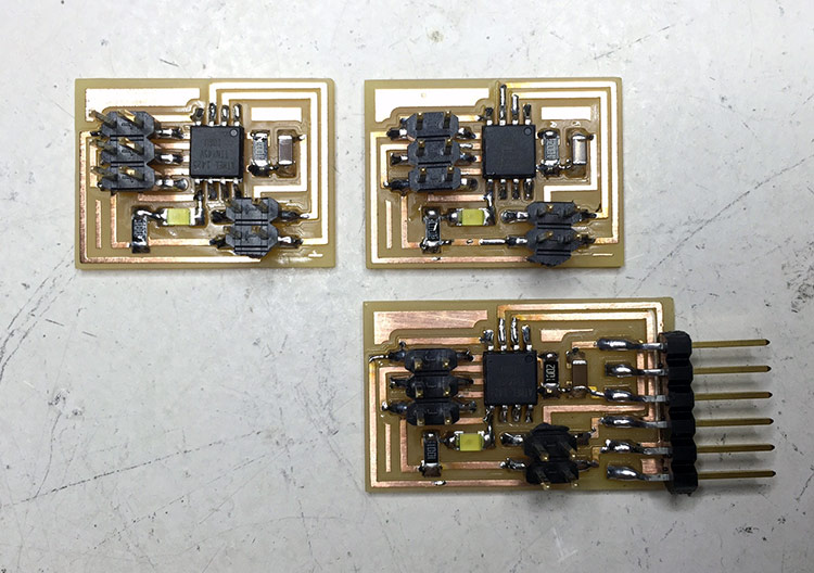
Software used:First I milled the 3 boards, 1 bridge and 2 nodes. Soldered everything, and that's it:
Programming
To program it you can follow these steps:
1) Download the C and MAKE files, put all in the same folder and run on Terminal:
make -f hello.bus.45.make program-usbtiny2) First program your bridge without change the C code.
3) Then change the hello.bus.45.c code in line 41 to program the NODE 1:
#define node_id ‘1’4) Save the file, connect your ISP to NODE 1 board and make program again on Terminal
5) Repeat steps 3 and 4 only changing the number of node_id ‘x' and connecting your ISP on the respective board.
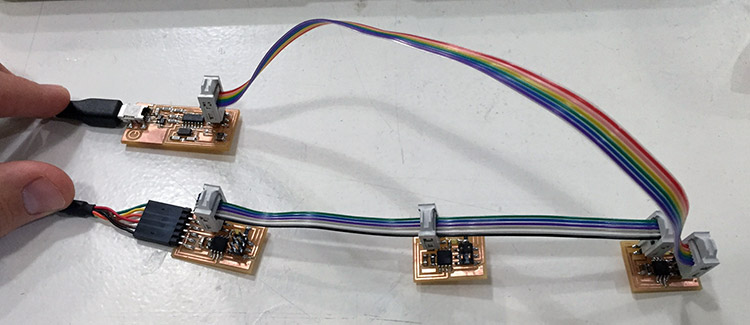
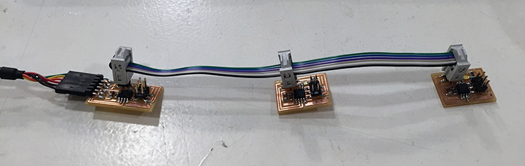
Connect bridge to USB by FTDI cable, and all the nodes in bridge on the right sequence:
To talk with the board you can use Arduino IDE. Open it and set board and processor as Attiny45, and open the Serial Monitor. If you type the node number it should blink twice, as you can see on video:
Note: Before it works I had some problems with the LEDs, I discovered that it was on the wrong side, then I changed all the LEDs and it worked.
After that I tried to play with serial communication using Arduino IDE and other board that I made a couple of weeks ago. What I did was turn LED on sending data from my computer and receiving a feedback from the board, as you can see on the video below.
You can see the Arduino code below:
fab FTDI cable (extra)
We finally made our own Fab FTDI cable. After a couple of weeks using this cable you realize that you will need it a lot, so first thing to do is google it to buy one, and then you discover that it is expensive, but you can make it! So let’s do it!
Ferdi found an FTDI cable in Sparkfun and took the eagle’s schematic to adapt in a more fab version, only one layer and inventory components. After that he asked me if I could help trying to produce the board, and so I did it. The first version was still with very small resistors, so we changed it and after soldering using, for my first time, Flux to help with FTDI’s chip small legs, it surprisingly worked.
Note: You will need to use a 0.10” milling bit, which require some extra care because it's super fragile, check in my final project page some tips to use this tool.
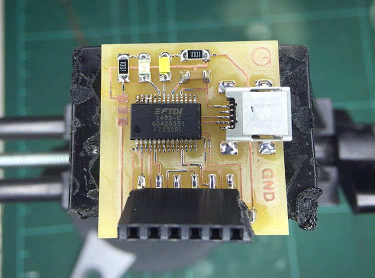
After the first trial our electrical expert, Jani, improved the board design changing the female connector position and adding a voltage switch, which can make the FTDI cable provide 5 or 3V. Check the final version:
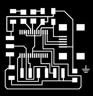
Check the bill of materials to make the FTDI board:
| Qty | Value | Device | Package | Description | |
| 1 | - | M06SMD | 1X06-SMD | Header 6 | |
| 2 | 0.1uF | CAP-US1206FAB | C1206FAB | Capacitor | |
| 1 | 10uF | CAP_POL1206 | EIA3216 | Capacitor Polarized | |
| 2 | 1K | RES-US1206FAB | R1206FAB | Resistor (US Symbol) | |
| 1 | FT232RLSSOP | FT232RLSSOP | SSOP28DB | FTDI chip | |
| 1 | Green | LEDSMT1206 | 1206 | LED | |
| 1 | Red | LEDSMT1206 | 1206 | LED | |
| 1 | - | SPDTSWITCH | SPDTSWITCH | Voltage Switch | |
| 1 | - | USB_MINIB | USB_MINIB | USB connector |
You can download the schematic and board design files here.
| ← week 12 / composites | week 14 / interface and application programming → |
|---|