Final Structure
After completing the first working prototype, I redesigned everything in Autocad and Rhinoceros and came up with the final structure that takes account of all the problems and issues emerged in the prototyping:
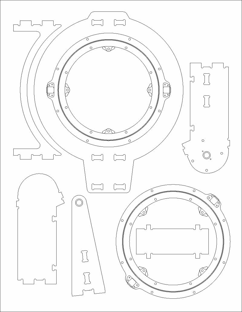
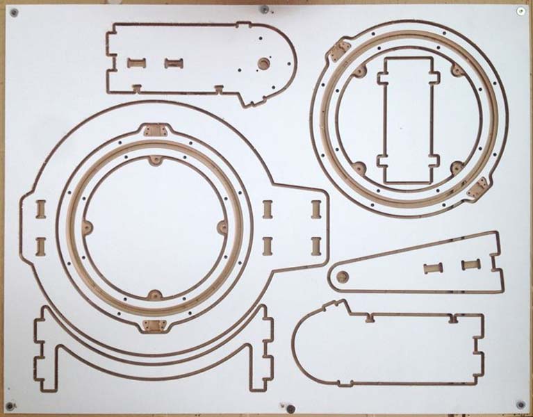
CNC milled structure
The design lays on a single 930x720mm sheet of 12mm MDF. I painted one side of the board with white chalk primer paint the day before milling. This part can be avoided by using a laminate board or skipped completely, but the machine won't be as sexy in the end!
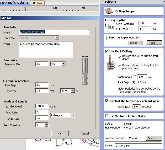
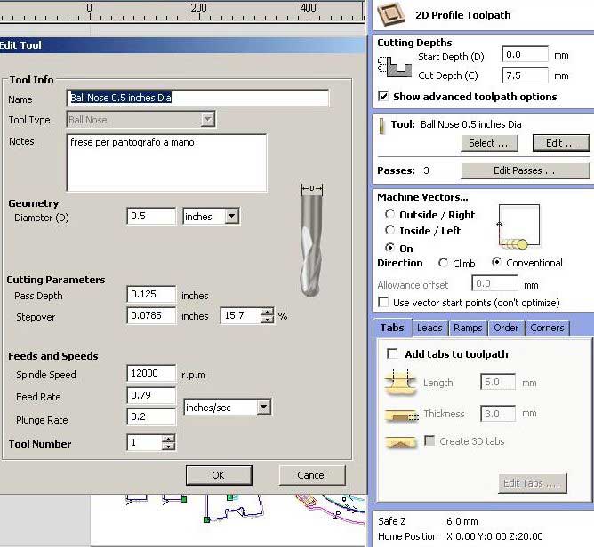
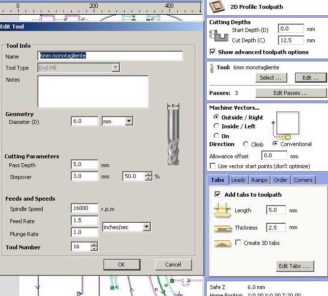
The toolpath list is very complex and opimized to assure a fast and safe job. It starts with the 3mm drilling with a simple drill tip, then you change the tip and load the 12,7 ball tip to engrave the steel balls canal, then the last change using the 6mm single blade upcut tip that makes the pockets first, then the inner cuts and moves to the outer toolpaths.
Toolpaths list
The design lays on a single 930x720mm sheet of 12mm MDF. I painted one side of the board with white chalk primer paint the day before milling. This part can be avoided by using a laminate board or skipped completely, but the machine won't be as sexy in the end!
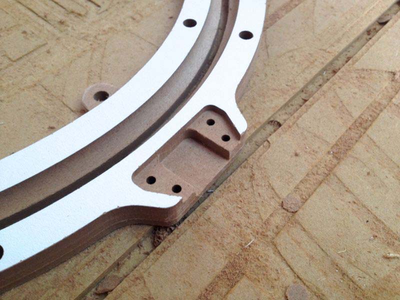
Assembly
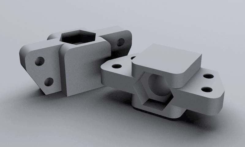
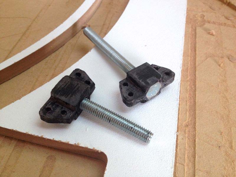
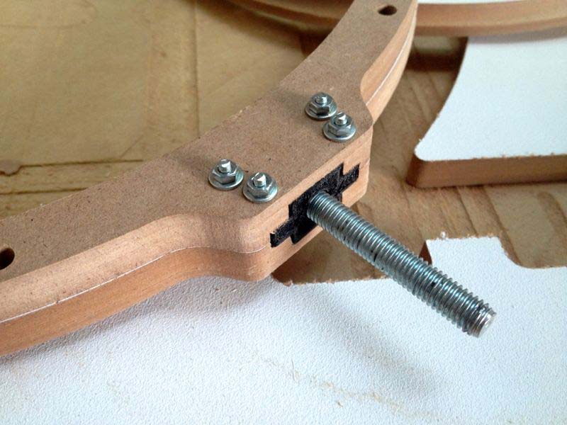
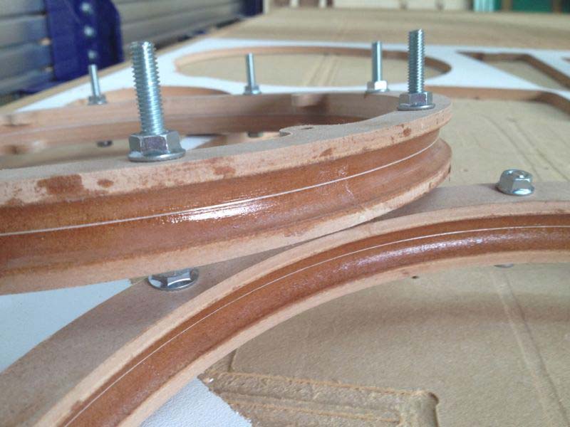
The first step in the assembly is to close the outer ring and both M8 shaft supports together. The support is 3D printed to perfectly fit the pocket in the MDF and the M8 bolt is first heated, then placed in the support so that the hot bolt can melt the PLA a little bit and be secured in the support. Both supports are placed in the outer ring sandwich and secured with M3 screws.
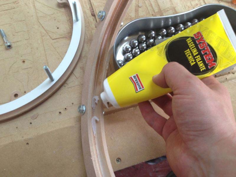
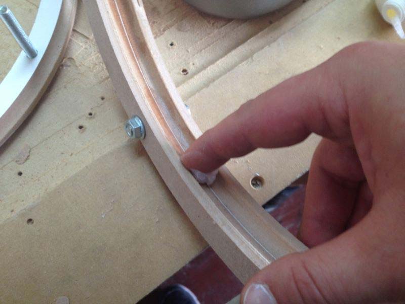
The canal in the two rings is first cleaned with sandpaper, then vaseline grease is applyed to lubricate it. The outer ring is assembled with bolts and the steel balls are placed between the completed outer ring and half inner ring. When the balls are all in place, the other half of the inner ring is closed with bolts (those bolts are longer as they have to hold the bevel ring).
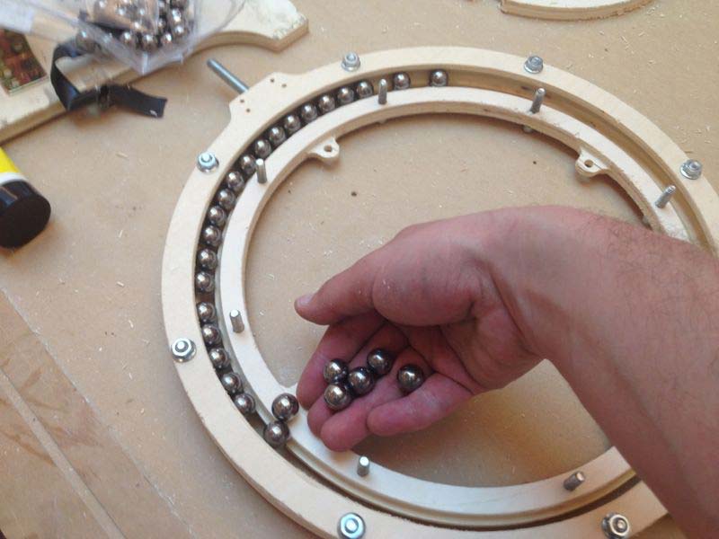
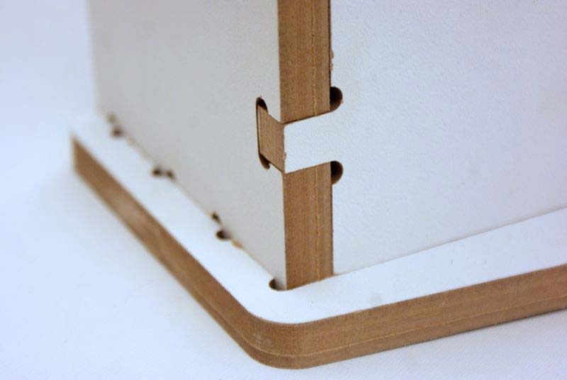
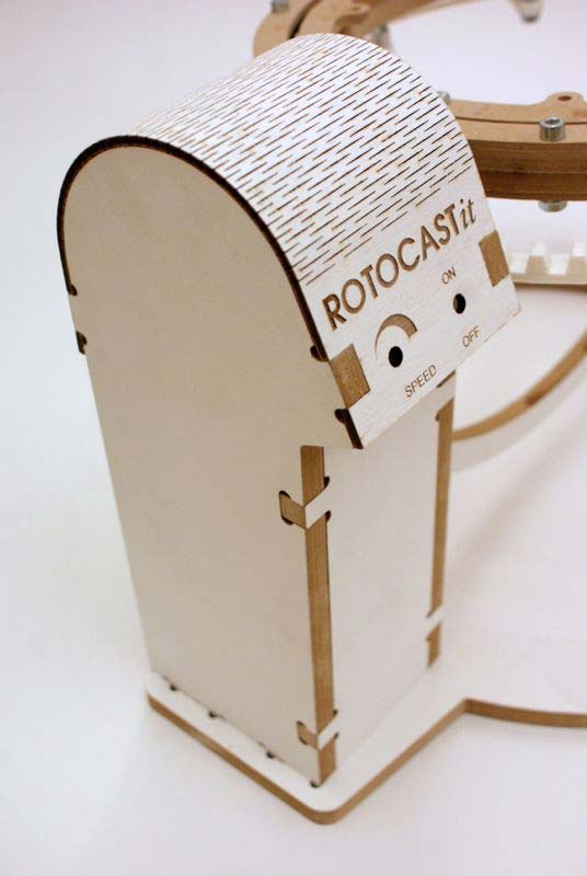
The structure features cnc'ed finger tenons, pockets to hold metal ball-bearings that supports the rotating ring, inner ring and outer ring connected by 66 steel balls, a lateral "turret" that holds the motor and electronics, covered with a kerf bent 4mm plywood panel.