WORKING PROTOTYPE
Building the main bearing's assembly was the first task I wanted to complete to understand if the "bearing system" would actually work. Therefore I took the bearing I already made and "built over it", just to see if my idea worked, already knowing that in the end I'll have to redesign the whole structure, but, at the moment, and given the short amount of time, that was the best way to follow.
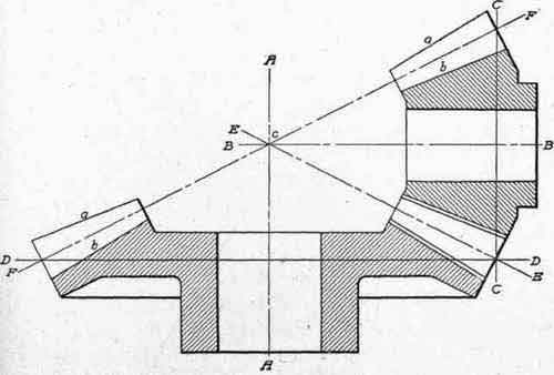
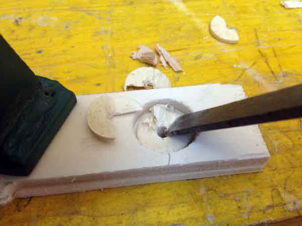
Designing a Bevel Gear
I designed the bevel gear in Rhino. At the beginning I had no idea how to do it, but I understood that to draw a bevel gear, the only thing you need is a cross section. The bevel gear I designed has a very large 77 theet gear and a small 11 theet pinion. The ratio is 1:7. Using an even number of theet is better because the same theets never touch twice in a row, reducing stressing and tearing.
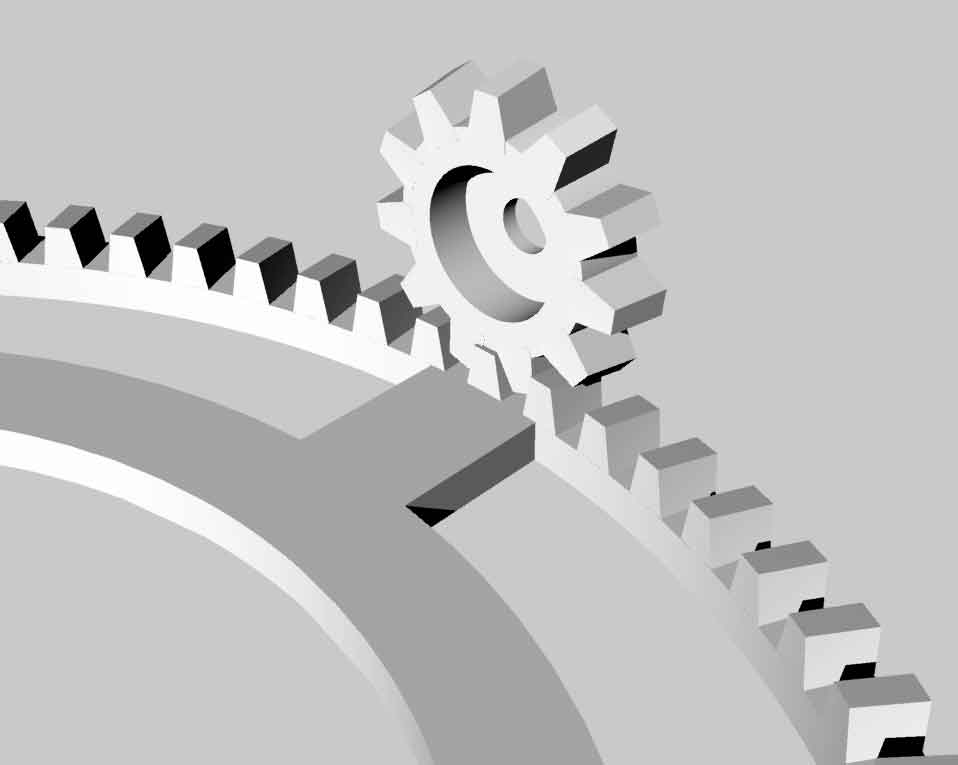
After designing the bevel gear I 3D printed it in four separate quarters to fit in the 3D printing bed. I also designed a support for the shaft upon which the outer ring would rotate. This support is of course a temporary solution, as in the final design they will be integrated in the body of the outer ring.
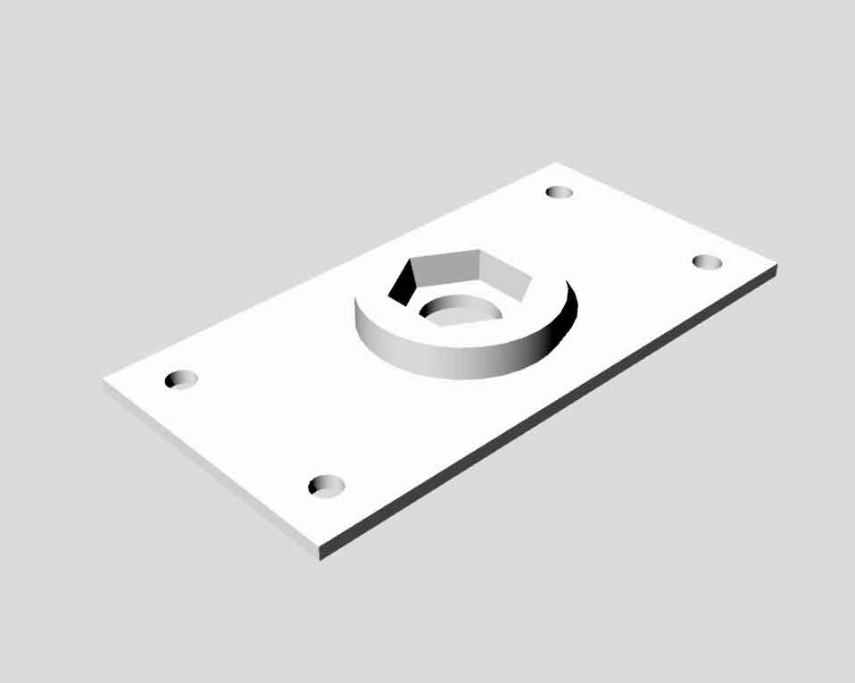
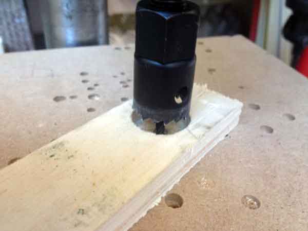
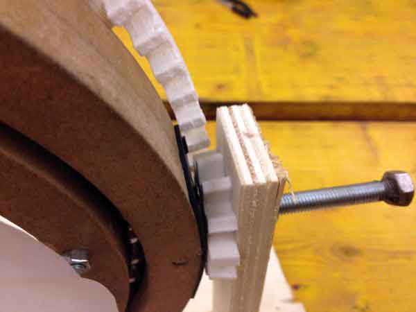
Mounting the 3D printed bevel gear and pinion onto the ball-bearing structure already gave me some hope it would work, so i rushed the construction of a base support. I just used some scrap wood, and two metal 608zz ball-bearings I had laying around. The following pics show a "Ghetto ball-bearing support" anyone can made in no time taking good advantage of plywood's features.

Prototype Assembly
The 3D printed shaft holders were strong enough to hold the ball-bearing structure in place without major disallignment, so I installed the four 3D printed bevel gear's quarters on the inner ring, the pinion to the shaft and mounted the ball-bearing structure with M8 shafts onto the base supports.
Success! Everything worked fine!
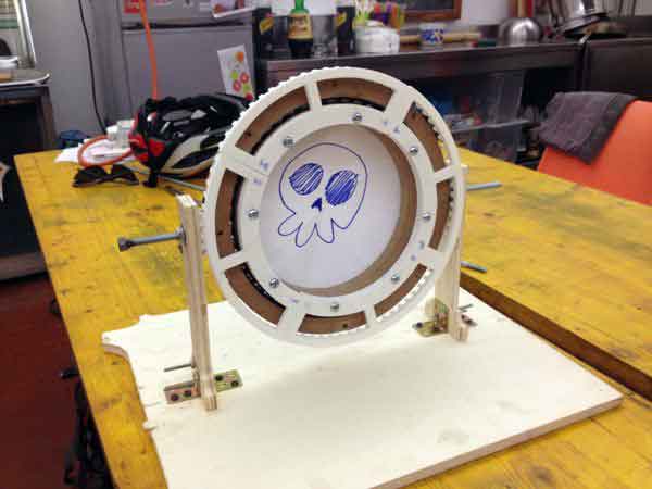
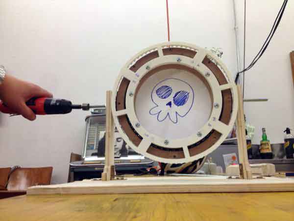
The machine moves pretty smooth, given the unreliable and temporary design of the structure. The skull I put in the machine goes back to its original position after 7 full turns of the outer ring, respecting the 1:7 ratio of the gear's design.
I'm satysfied with this result, the next step is to design everything to be easily fabbable and to improve electronics and controllable dc motor.