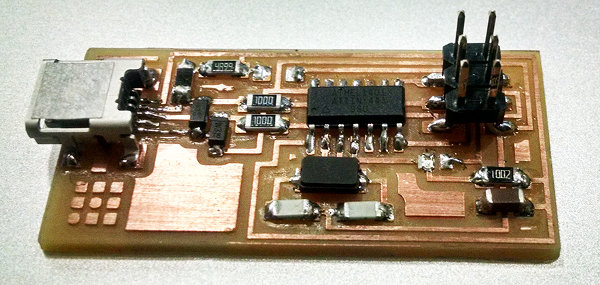
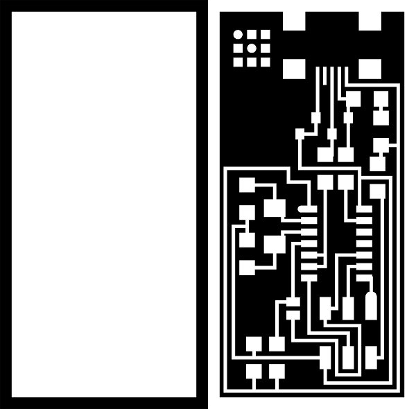
For this week's assignament I had to make a circuit board, a fab-able in-system programmer (FabISP) through the CNC Milling Machine. The FabISP is an in-system programmer for AVR microcontrollers, designed for production within a FabLab. This allows me to program the microcontrollers on other boards I make, using a USB cable and 6-pin IDC to 6-pin IDC cable. It's based on the USBtiny and V-USB firmwares, which allow the ATtiny44 to perform USB communication in software. There were 3 different PCB matrices I could choose, I chose FabISP Neil. I first downloaded the traces and interior images from the FabModules to send them to the milling machine.
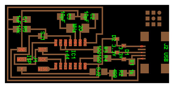
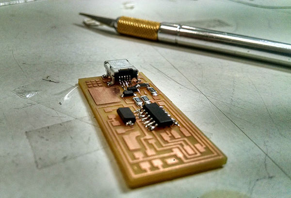
It consists of components like a processor core, and programmable input and output devices (ATTINY44A), 3 capacitors, 7 resistors, one USB cable connector for a direct control from the computer, a pin header, 2 jumpers which would later be removed. Finally, 2 diodes zener 3.3v, and a 20MHZ Crystal, which works as an electronic oscillator circuit that uses a vibrating mechanical resonance of piezoelectric material to create an electrical signal with a very precise frequency.
_MILLING THE BOARD
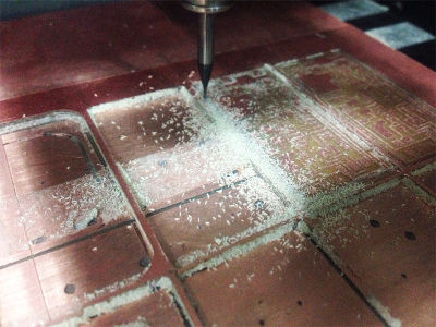
For milling the board I used the Roland Modela MIlling Machine (MDX-20). Before starting to mill, make sure the Modela machine is clean and set two boards on top of the metal plate to avoid breaking it while milling, make sure they are both flat and lock the metal plate to the machine with its screws.
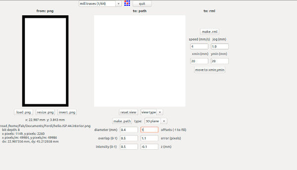
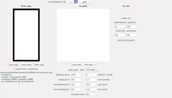
There are two milling bit sizes, 1/64 for the traces and 1/32 for cutting. So once in the Modela software first mill the interior image of the board to make sure the machine is correctly setted:
Make input: images.png to output:RolandMDX-20.rml
Press VIEW botton to set the X and Y origin. Lower it until it smoothly touches the copper plate for setting the Z origin.
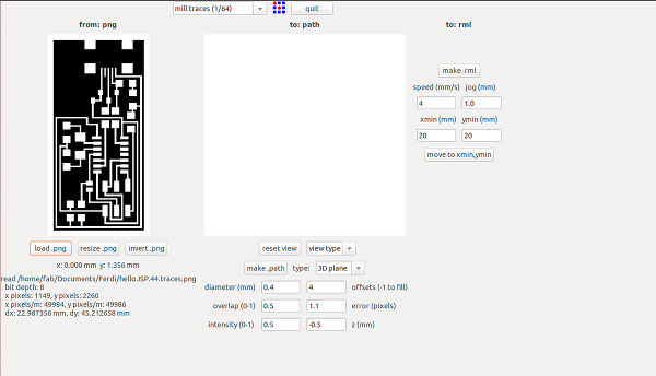
Load the right .png
Set the traces parameters
5.Make path
Make rml
Begin the milling
For the traces, make sure to insert the new presets and repeat the steps.
Finally, insert the cutting presets for cutting the board.
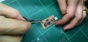
_SOLDERING THE BOARD
For soldering the components follow the tutorial linked in Troubleshooting column; it clearly explains the orientation of each component as well as some useful tips to make it work.
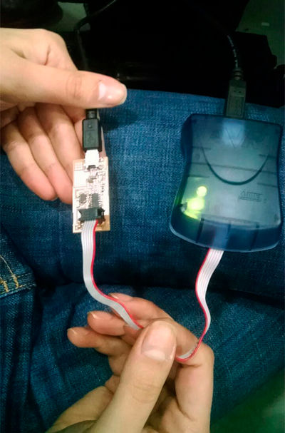
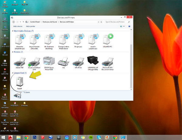
PROGRAMMING THE ATTINY44
After soldering the components, I went through the "Smoke Test" and the board was not getting any power, so I fixed some of the welled joints and finally it worked. For programming the ISP board I installed ATAVRISP2 programmer and followed the FabAcademy Tutorial which also gives useful tips on how to solder the components properly, for example start from bottom to top, and from inside to outside. Once the board was working, I downloaded the Firmware archives and opened the cmd terminal. Inside the firmware folder, I programmed the board through make clean, make hex, make fuse and make program comands. Finally I took the Resistors 0 ohm and now my FabISP device has been successfully programmed and is recognized by my computer!.