Final Project
Hand-E: What is and what it does?
Hand-Exercise is the name of the device I developed as a final project. It help people with degenerative diseases in their hands, such as osteoarthritis to perform the necesary exercises that improve and maintain their mobility, strengthening muscles and tendons. This device is particularly suitable for people who have lost considerable mobility. Excercises not only prevents stiffness, but the loss of muscle mass, which further worsens the condition.
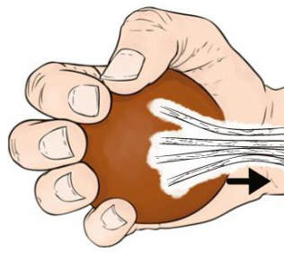
Basically, the Hand-E simulates the excercises that patients perform with a rubber ball.
First steps: Designs, Materials, Control System
From the beginning it was quite clear how I wanted to make the prototype, but from the idea to the materialization of it there is a huge way.

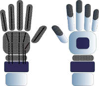
The first sketches of the Hand-E.
Find information on how to make the device was not at all easy. I needed beacouse I don't have deep knowledge of anatomy and engineering, I just have the information that I need to make rehab with arthrosis and info related to the disease. All available information is on prostheses, there are hundreds and hundreds of projects on hand prostheses and thousands of documents about it. But this device is not for those who have lost the hand, so here came the big challenge.
These diseases often degenerates finger joints, so the idea to use rigid parts was dismissed from the beginning. Also I have to be aware that a majority of people who suffer these diseases are elderly and should be a practical device for them.
I knew I wanted to make a kind of template for the palm, simulate the tendons with filaments to move it with motors, and make a box with the control system as a bracelet, containing the circuits and motors. It was clear I did not wanted to make or wear a glove and that the part for the palm would make with 3D printing in a flexible material. But not everything that you plan can be carried out, and I could'n print the templates parts I needed to make the test, and the time jumped on me unable to do these tests, so I had to look for alternatives. One of them was to make a glove with a textile-based neoprene for sewn over cables, but other than which did not convince me, the machine that could sew with tubes and wires did not work.
Trying to sew the transmision cables to the neoprene.
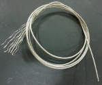
While thinking about the solution, I made the tests to find out what type of material would I use to move the fingers (tendons). My first idea was to use Flexinol, but it did't apply because, among other reasons, would not have the enough strength to bend and straighten the fingers. So the next selection was the nylon filament, but the problem was the return of the finger to the original position, and I did'n want to add any other component that might be uncomfortable for the patient, such as springs. There was some solutions as flexible cord or flexible resin, but these solutions forced me to put something over on the opposite side of the palm. So I find some nices projects on internet that used push/pull cables. So I decide to test with bicycle brake cable. For for tests it worked really nice. But I needed a thinner clable, so I find a 1.1 mm transmission cable wich work correctly pushing and pulling the fingers.

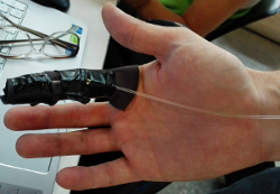
We perform some test with for the filaments for the tendons, and to see if pulling, all the phalanges b bend enough, is not it just to tilt a finger tilt, but bend all phalanges.
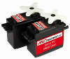
The next was select the servo motors. From the beginning I thought I could use mini servos, but those with sufficient power are quite expensive, so I had to try different powers to know which to use. I needed enough power to move the fingers, because although there are people who have lost mobility, the servos can found some resistance. And to make those test, we design on Solid Works a finger to laser cut parts in wood. For some reason, the dimensions of the laser cuts was wrong, and we got a really big finger (we call it "Yeti's finger").
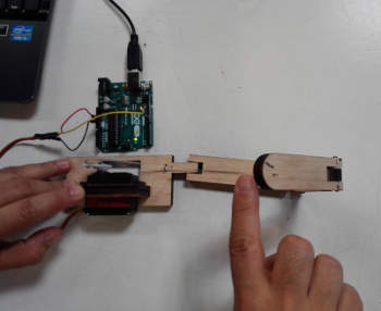
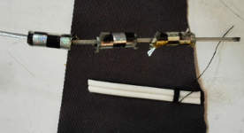
With the Yeti's finger we made the servo motor power test, and in general the push/pull cable system test.
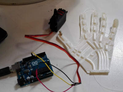
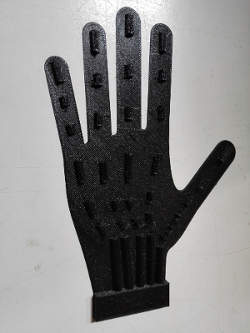
For the palm part, I print in flexible nylon this part with the hand shape we found in internet that helped me to test the flexible material and cables, in a more accurate way, with all fingers. Finally it was impossible to use my original idea for the main part of the device, the palm, so I had no other other option but to to make quickly design the palm of my hand and adopting the system we use in the test. The original idea was to make it more thick, not with ducts for cables by way of pipes, but solid parts segment
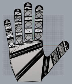
This design is close to what I was searching for the main piece of the device
Assembling the device
Once I made all the test It was time to put the pieces together. The first step was to print the final part of the palm of the hand. I printed in flexible nylon PLA with my RepRap 3D printer. The result was surprising in material and finish of the printer, but was not my ideal piece for the prototype, too thin for my liking and with very thin tubes that suffer with the rubbing of the wires. Better squares tubes than circular and not so thin to make it easy to introduce the wires, and with thicker walls.
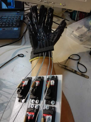
Testing how the flexible part works with the push/pull cables and the motors.
The next step was to design the box for the control system (servo motors and circuits) in Solid Works: a piece to fix with screws the five motors, the box for the servos and the PCBs, the bottom piece of the box, and two pieces to fix de hand palm with the cables to the box. Our instructor Ferdi, teach us how to make simulations in Solis Works, including servo motor designs that you can download from internet.
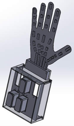
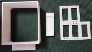
The main parts of the control system box, 3D printed with PLA.
Once we assembled the motors and the cables were placed on the flexi nylon palm, we can do the first tests of operation and write the first version of the code. I decided to use Arduino to avoid problems with my Windows 8 OS.
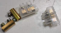
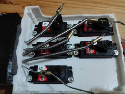
To fix the cable on the servo motors control horns, we use metal cable conectors, without the external plastic part. At right, the 1.1mm transmission cable. Note that with this cable, it was impossible to fixing the ends with some tin, because it repelled, and the lead balls doesn't was enough, so I had to use some dromps of super glue.
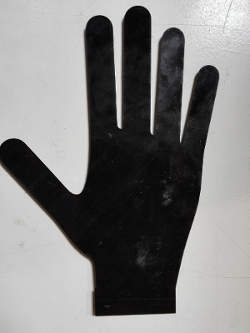
With this piece was inevitable not use a glove or something similar. I could not perform any other test to get close to my origial idea, so I had no choice but to use the option that least wanted: the glove. So I fix the flexible part to the glove by sewing the sides of each cable tubes. The best thing would have been to use epoxy but there was not enough time to do more tests, so we tried to play it safe.
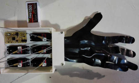
And if it was hard to make test with the device in my hand when I could not count on someone, I decided to finally fill a glove and attach it to the control system box.
My concern was that not all phalanges were blended, so I tried to put some balls of lead in the joints, but it was not entirely effective. We did some tests and managed to bend all phalanges.
Electronics and programming
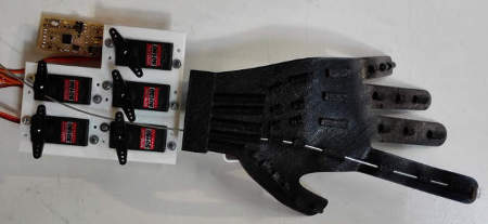
To control the five servo motors, I decided to use a Fabduino board. All I had to do, was a small shield to connect the five motors and the power supply.
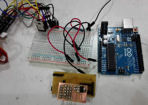
We perform some preliminary tests with an Arduino Uno board and a breadboard, then I made a Fabduino, wich use a ATMega 328 5v 16Mhz and the shield.
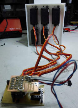
The Fabduino board and the shield to connect the battery and the servo motors.
The original design of the shield included a 5v voltage regulator. We made test with the servos, but when I assembled all the system it doesn't work. So finally we desoldered the regulator and use a 5v power supply.
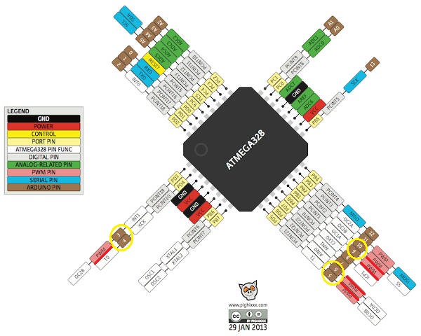
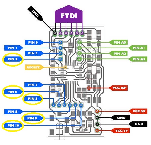
The processor of the Fabdino, the ATMega 328 5v 16Mhz, just have 6 pins with PWM (Pulse-With Modulation), a technique used mainly to allow the power supplied control to servo motors for exaple. So is really usfeull to read the processor data sheet, or use the Pighixxx usfeul pinout diagrams to know what pins can we use for our servos, and compare with the Fabduino diagram to connect all the system correctly.
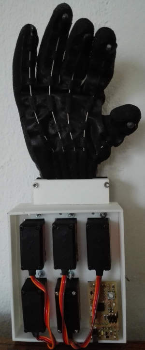
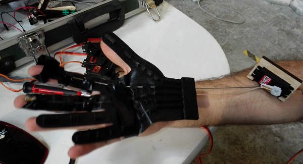
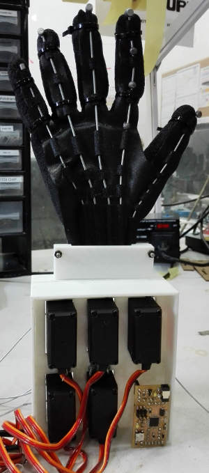
The wires that move the fingers...
A systm of push/pull cables connected to a five servo motors move the fingers. THe servo motors are installed in a control system box with the circuits. But befor test, test and test, I decided to redesign the box. The position of the servo motors inside the box was not correct, so I decided I should put them in the position it had originally planned, ie, as an arrow and something more separate from the hand. In separate tests the system worked, but it did't work when connected all. So I have to redesign the control system box, but for the presentation there was no time, and also back to the original idea to make it in transparent acrylic, wich is much more resistant than the 3D printing for this kind of devices, when there are a lot of movements and forces.
Another thing that does not convince me and eventually didn't run correctly, was the system for fix the cables to the servo horns. I had to adjust motor by motor the position of the system and the position of the horn at the servo point 0. But whenever I do the test, the position changed, so in each test, I had to re-calibrate the system. I thing there if I connect the cable directly to the horn it should works. Finally I had to put a piece of the internal metal part of the bicycle brake wire, for directing the return of the cable, but with the fixing system of the horns, it was a nightmare. So if you want to replicate, pleas take note that is better to increase the separation between the hand system and the motor, increase a few millimeters over the separation of the palm output cables and the motors and of course, assembly the motor in an arrow-shaped to avoid the motor horns collide. The metal tubes to prevent cable bending when returning to the original position, should go into the pieces that hold the printed palm, right where the cables, thus will not move at all out, preventing collide each.
In in the post-test phase, assembling all the parts the system got worse, despite all the tests that worked! Lesson learned: the fact that the system works separately, does not mean that the assemble work.
List of components, features and files
- 5 RC CYS-S0150 15kg metallic gear servo motors
- Voltage: 6.0–7.4 v (2.7 - 3.2A)
- Speed: 0.1– 0.14 sec/60º
- Torque: 14-15 Kg.cm
- Size: 40.8x20.1x38mm
- 300 mm push/pull cable (transmission)
- 5v 5.0A Mean Well power supply (RS-25-5)
- 5 wire conectors
- Fabduino board (find all the instructions and files in this link)
- Shield components (Eagle files):
- Board
- 1 x 1x5 pin header
- 5 x 1x3 pin header
- 1 x 1x2 pin header
- Control system box: Solid Works files
- Hand palm: Solid Works file
- Glove
- 10 Lead balls (for fishing)
- Screws, nuts and washers
- USB FabISP to program the Fabduino board
- Code: Arduino file
- Computer-aided design: used for the first sketches, the final "hand" part "Yeti's finger", Controls System Box designs
- Computer-controlled cutting: laser cutting for the "Yeti's finger" test with servo motors and the transmission cables (tendons)
- Electronics production: Input and output device (originially I wanted to use a potentiometer to control de speed of the fingers movements), and finally, for the Fabduino and shield boards.
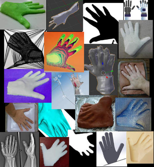
- 3D printing and scaning: I scan my hand with several techniques and devices, finally I 3D printed the palm part of the Hand-E with flexi nylon filament.
- Electronics design: Input and output device, and for the servo motors shield board.
- Embedded Programming: Input and output device, and finally, for the servo motors.
- Input/output devices: Potentiometer and servo motoros PCBs
Digital Fabrication: Which processes were applied?
The following processes were those used in both the design phase (with several assigments) and the development:
Conclusions
Ok, ok, it's just a prototype! Your first prototype of this kind! Certainly, but anyway, you want to keep everything running and out as you had planned from the beginning and throughout the course.
The challenge was not easy, mainly for two reasons: first almost all the documentation that you can find on internet is about prosthesis, but we don't need a prosthesis, the potential users of this device have their hands. Second: I have to keep in mind that most patients who need rehab with this device are elderly, and also, many have deformations in the finger joints. For this reason the device must have a conception and design as simple as possible and also be as comfortable as possible, that does not hurt them or disturb them.
The most important objective was accomplished, I learned a lot. And now I understand what it must be corrected and how.
And another important thing I've learned is that despite that you plan the work unforeseen included, you must include the triple, as said Neil! And follow your intuition without fear of making mistakes, and if you mess up, you've learned, follow your intuition.
You can find more information about the Hand Exerciser project on the Applications and Implications assignment webpage.

Hand-Exerciser by Milena Orlandini is licensed under a Creative Commons Attribution-NonCommercial-ShareAlike 4.0 International License.
Fab Academy 2015 website by Milena Orlandini is licensed under a Creative Commons Attribution-NonCommercial-ShareAlike 4.0 International License.
