Output Device
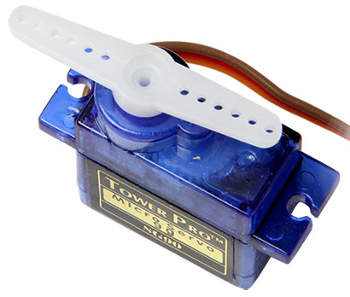
In this assignment we have to design, build and program an output device PCB. I select a servo motor circuit to use with my potentiometer input device, which in all likelihood I will use in my final project.
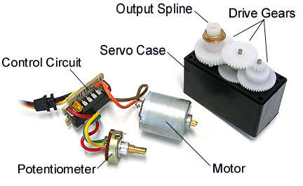
The servomotor system is composed of an electrical motor, a potentiometer (sensor system), control system (circuit), drive gears, the output spline and the servo case, which contains all the above elements. A servomotor basically is an electrical motor wich can be controled in speed and position due to a sensor system (potentiometer), and use the PWM (pulse-width modulation) to do it. The servo has the capability to be placed in any position within its operating range and stay at that position in a stable way. They are widely used in robotics and modelism projects, besides in industry.
As in all electronic projects, you must first design in Eagle the circuit with all its components, as we have been doing so far. You can download the schematic and board files.
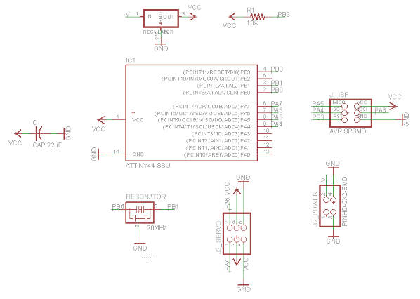
This is the BOM for our output device:
- ATTiny44A SSU
- 5V Regulator (ZLDO1117G50DICT-ND)
- 10K Resistor
- 22uF Capacitor
- 20 MHz Resonator
- 2x3 STM Header (ISP)
- PinHD-2x2-SMD (power)
- PinHD-2x3-SMD (servomotors)
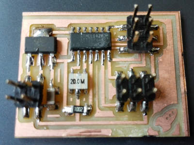
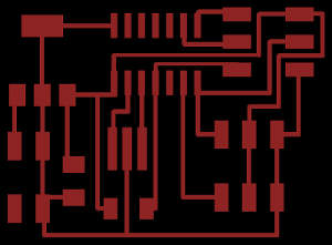
Once I have prepared on Gimp the traces and outlines PNG files, I milled the board in the Roland SRM-20 milling machine. Despite being the fourth assignment in which we manufacture PCBs, I had several problems when milling the board. First, because at some stage of circuit image processing, the image changed dimension, so when soldering pads did not coincide with the components. Later I had many problems with the outline: the router first made the cut of the board in small size, amid the traces. Then don't cut all four sides, just three, and finally the machine just performed the action without getting to the point z = 0... due to a problem with the way the bit mill was installed, it just not have to be too high or too low.
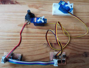
Finally, I soldered all components.
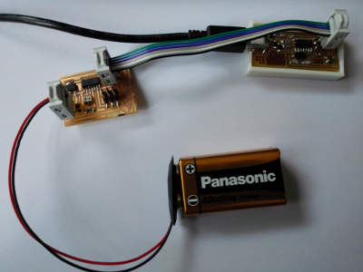
The next step was to program the ATiny44 with our FabISP, supplying the microprocessor with a 9v battery.
Due to problems caused by Windows 8 OS, I can't program in C with my computer, neither I can't use Linux with W8... and of course I don't want to be depending on other people's computers to program my PCBs, I had to program with the Arduino IDE. So I upload the sweep Arduino example only to verify the correct functioning.
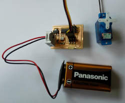
But I find more problem, servos I had asked for the assigment was not ordered, so I had to use some recycled .... which turned out to be hacked ... So if you do not use new components, it is better check proper operation before.
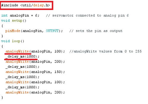
And some other problems, the servo library from Arduino doesn't work with ATtiny44, so we had to make some changes. First, eliminate the servo library and use the delay one, and then use the analogWrite command. Then, use '_delay_ms(1000)' from the C Neil's command, instead the delay Arduino's command. You can download the final program .
Anyway, just to understand the C program, we upload it on a Mac computer and check how it works.
Finally, after many problems and attempts, the servomotor ran.
To complete the exercise, I made some test, changing the differents values.
The objective of the assignment was to made an output device, in my case with a servomotor, but I want something beyond and control the servomotor with a potentiometer (I made a potenciometer PCB in the Input Device assignment), but because I can't connect the PCB's en an easy way, I decide to make a Fabduino Kit PCB. At the moment we don't have all the components, so I have to wait a few days to make it. When I get it, I will update the web page.

