Computer-Controlled Machining
Making something big
This week we had another close encounter with the digital fabrication machines, but now, we was talking about big machines, Computer-Controlled Machines.


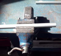
Our CNC Milling Machine at FabLab Barcelona: Precix 111000 Series, at left, and ShopBot PRSalpha 144 at right.
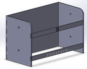
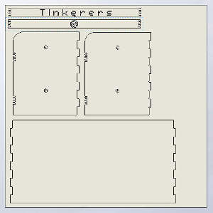
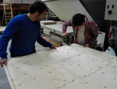
The assigment for this class was to make something big! Once again I think of something for the final project, but does not apply, so I think something useful that also allows me to practice various techniques we have been studying. After discarding several options I decided to manufacture a piece of furniture for our Tinkerers - Fab Lab Castelldefels project: a tape and filament dispenser. The result was not as great as it was designed, because I did not realize that by choosing playwood to work, I had only half of the board!
But first of all, I will give an overview of the most important points to consider.
With CNC machines, we can make amazing things. We can cut and engrave with differents types of bits, to make 3D or 2D objects in many differents materials (woods, foams, etc.).
To create this amazing works with CNC techniques, we have to considere a lot of important things, depending on the materials and the objects we want to make.
First of all, we need to talk about the bits and endmills, wich are the stars of the CNC milling machines.

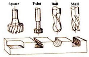

There are many types of endmills, depends on material and work to be done: cut, reduce, drill, engrave, etc. Basically changes the shape of the lower end, and the number and direction of the flutes.
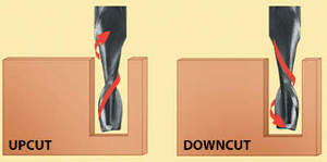
Depending on the direction of the flutes, there are upcuts and downcut bits. The first one, clear chips from the kerf and allows faster feed rates. Downtcuts, push wood fibers down for a cleaner top suface, and require slower speeds rates.
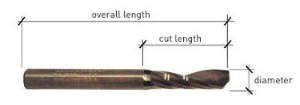
We also have to check the bit measures, such as bit total lenght, flute lenght or bit diameter to configure the software settings.
There are a lot of possibilities to design the object you want to mill. If you are going to mill a 3D object, you can design it using Rhino and the RhinoCam plugin to make all the settings, and generate the G-code files. You also can use any freeware software. If you mill a 2D object, you can simply design it in Inkscape an use a G-Code generator plugin. The best way to design an object to be processed by a CNC machine is a CAD/CAM software. CAD (Computer-Aided design) is a general design software. CAM (Computer-Aided Manufacturing) is a specific design software to work with CNC machines. It converts CAD designs into a CNC machines instructions, to produce an object.
In my case, I decide to use Solid Works, a really powerfull CAD/CAM software (Solid Work files, Inkscape file).
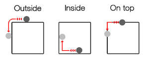
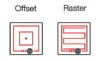
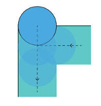
As we need to configure the software to take instructions to machines, we need to consider some basic notions about the toolpath. We have Profile, Pocket and Drilling toolpath. We use Profile toolpath tu cut. We can make three differents Profile toolpath of the line of our design: Outside the line, inside the line, or on top the line. Pocket toolpath simply cuts pockets. We have two options with pocket toolpath: offset or raster, with the same final results. Finally, drill toolpath is just to make drills.


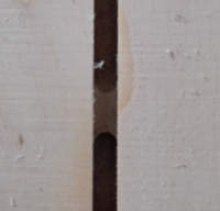
With the CNC milling machine, we can make drills, pocket and profile cuts.
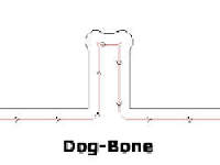
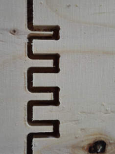
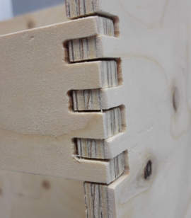
Another thing to keep in mind when designing an object, is that the bits are roun and make circular cuts, which complicated the task of getting angles. There are some techniques that if can not get a perfect angle, allow parts fit correctly: dog bone fillet technique! If you're not convinced with this technique, you can simply follow a few milimeters in a straight line, but keep in mind that all these maneuvers with the router, will add work time.

If you need to assemble your milling pieces you must need to use joints. You can design your own, or can be inspired by 50 Digital Wood Joints from Flexible Stream, an open source design webpage.
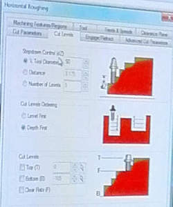
Once the object was designed, we have to create a G-code files. G-code is the programming language most used with CNC machines. In brief, it's the language that tells the machine what to do and how to do. Depending on the type of design, we have to creat more than one G-code files: pocket and profiles, screws, milling tool diameter, etc. In the G-code files, you set the type of material, measures, type of bit, spindle speed, feed rate, plunge rate, etc.
With your G-code files prepared, you are ready to use the CNC milling machine. But firts of all, we must be aware that it's a machine, a large machine that just follow the software instructions and may be dangerous to be near. We must use eye protection, and never, never should be left operating without supervision.
Once we have check all safety measures, don't forget to check material measurement, these may not be exact to which manufacturer indications, so we must make the corrections in the machine software.
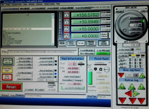

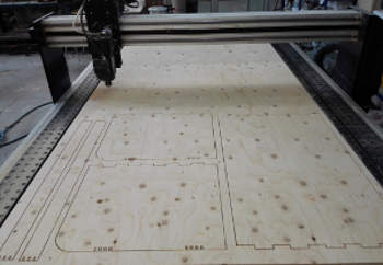
The next step is set correctly the 'Home' point, upload the G-code files and now, you're ready to mill and have some fun watching this incredible machine in action.
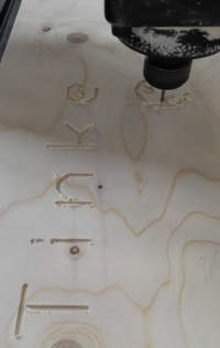
We upload the drills G-Code, to fix the board to the sacrificial layer on the milling machine, and we use a drill tool to this work. Then we upload the G-Code with the pocketing and profiles paths, and change the milling tool. In my case, I decided to use for all the work a 3 mm tool, because I had to engrave text and Fab Lab Logo, and then for the joints of the small frontal tables that had a small dog-bones. I use the text sketch from Solid Works, but it is recommended use CNC specific fonts. We had to correct the pocketing tool path for the text on RhinoCam, and even that, some lines of the text were not engraved.
The tabs was generated automatically by RhinoCam. The role of the tabs are to fix the pieces to the board and prevent them from moving.
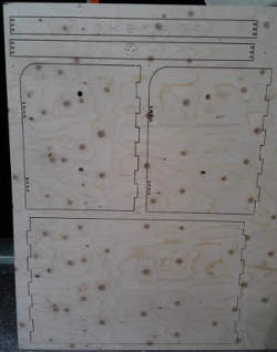
Once the CNC milling machine has completed its work, we vacuum the area, and check that the machine has cut all the pieces correctly. If it were not so, you have the chance to pass the router again with a few inches deep to correct the problem. Once you unscrew the board, you cant correct any problem. It was that happened to some of our group, including me. I checked some cut points and holes and unscrewed the board, but was not completely cut off...there was no turning back! So check first all the work. Since there is a sacrificial layer, it is worth add a few millimeters in cut depth or lower those millimeters in z axis when setting the zero point.
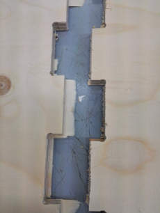
With the help of Santi, our local instructor, I used a jigsaw to cut the pieces. Normaly you use this tool just to cut the tabs. Even with the help of this tool, was unavoidable to have splinted parts, especially joints.
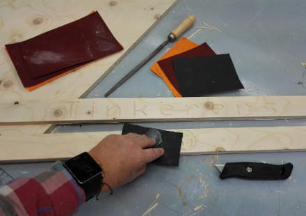
I had to use a lime tool to remove splinters, and sandpaper to polish. In this process the pieces lost material and the joints did not work at all, even if we add to each piece in the design two milimeters. So we need to use some white glue to assemble the pieces.
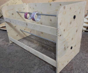
To complete the assembly, I use metal tubes for hanging tapes and paper rolls and plastic filaments. To prevent the tubes go out of their places, I designed a stoppers in Solid Works which I printed in 3D.
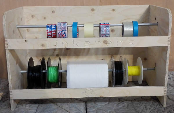
And finally we have our tape and rolls dispenser! Something usefull to organize our fab lab!
This assigment was very intersting, and we really need to read, and research a lot information. The CNC milling machines use a lot of techniques, need a lot of settings, and we need to control a lot of features, like the direction of the mill, speeds, steps, depths, etc. We learn a lot and the next step is to practice with different materials, diferents types of endmills, and diferent techniques.

Fab Academy 2015 website by Milena Orlandini is licensed under a Creative Commons Attribution-NonCommercial-ShareAlike 4.0 International License.
