Electronics Design
The Electronics Design assigment looked like something relatively easy to do. Not at all. But basically it was due to small details overlooked.
First of all we have to design a PCB, based on a model, and adding a few components: a button and a LED (with its corresponding current-limiting resistor), to get an a Echo Hello World board. It seems easy at first glance, but if you are not familiar with the electronics design software, is not so. Once you have designed your first circuit which can take many more hours than planned and desired, it is much easier. And what makes it even easier task, is to have some basic electronic concepts.
The software that I used to design my first electronic circuit was Eagle. Once you are familiar in the way it works, you can test and analyze other programs, like KiCad, but I chose this because it is my first contact with the circuit design, and is better be able to follow your classmates and instructors in case of doubt.
The first thing to do is load the libraries of Fab Lab where you can select the components to use. Once selected, we can make the circuit schematic with the connections. Do not forget to add grounds and VCC to the schematic, you can drive crazy finding ways to connect more than two routes to the same component!
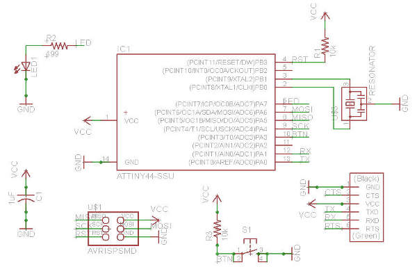
Once you have the electronic schematic, with the Electrical Rule Check made, you can design your PCB.
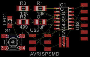
For a correct design you should carefully analyze what is the best placement for each component, before adding the routes.
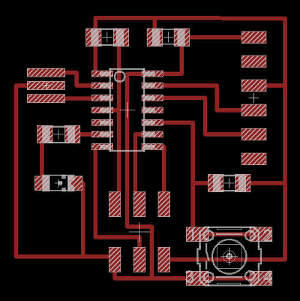
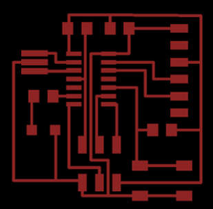
One of my little setbacks designing the connections was not find a way to move more precisely the routes, so I get some clearance errors, specially in the microcontroller area. It was as easy as modifying the values of the grid. Do not forget to load the DRC (Design Rule Check) Fab Lab file to make the check of your board (Eagle files).
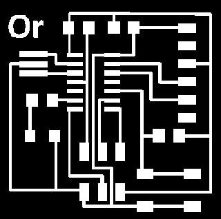

Once you have your PCB design, you have to export the file as png, to made the settings on Gimp or similar, to export the file to the milling machine, as customize it or made the outline (traces and outline png files).
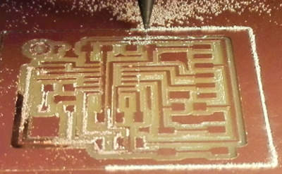
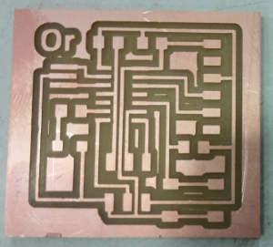
For the PCB milling process, we have to follow the same steps as Electronics Production class. Do not forget to precisely level the board on the milling platform... I have to mill twice my PCB due to this, adding a few tenths of a millimeter to milling depth.
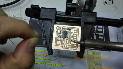
Already discussed in Electronics Production class: before soldering, we must be especially careful when selecting components. First, because they can be mixed, and secondly, because you can go wrong. Is not the same a 499 ohms resistance, than a one of 499K! And then, I wonder why my LED does not turn on! Once all the components are soldered, make a visual check of all joints and then, check the circuit with the voltimeter.
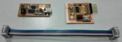
Now, we have all we need to program our PCB.
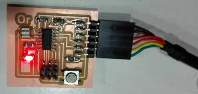
The last check of the PCB is to connect it to the computer. If the led light, and is recognized by the computer, we made it! But remember, if the circuit does not work, it may be because you have solder a wrong component...
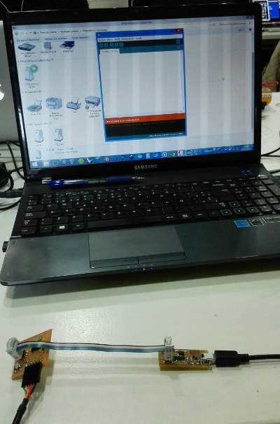
Now we are ready to program our PCB. I selected Arduino to make blink my led.
But my ISP spontaneously was no longer recognized by my computer. We spent a lot ot time trying to solve the problem, reinstalling the drivers and checking the solderings. We find the problem here, the miniUSB connections are very delicate, specially when connected and desonected often. So please, always check your solder joints. Also, we have already mentioned, there are many problems with Windows 8 OS and the ISP drivers.
But finally, we made it, and we run our Echo Hello World PCB. We even took the test by fading the Led.

Fab Academy 2015 website by Milena Orlandini is licensed under a Creative Commons Attribution-NonCommercial-ShareAlike 4.0 International License.
