Electronics Production
This week the assignment was to fabricate a PCB (Printed Circuit Board): mill the copper board, soldering the components and program the device . The objetive is to make our own ISP (In-System Programming), wich serves to program the AVR microntrontrollers. We used this FabISP to program all the circuits we made along the Academy.
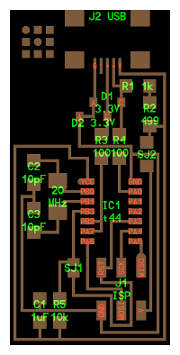
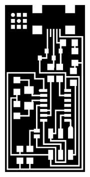
I used the Fab Academy circuit designs. In my case, I select the Neil's ISP model (helloISP44).
First, we need to mill the copper board with the Roland MDX-20 milling machine. This process is delicate because if the machine is not well calibrated the drills can break, damage the machine or the copper board. And if parameters are not well introduced, it will not be properly milling. In this kind of machines, we need to use the sacrificial layer to avoid damages on the machine. That means that we have to assemble, accurately, a board to place our copper board.
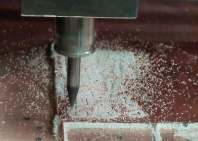
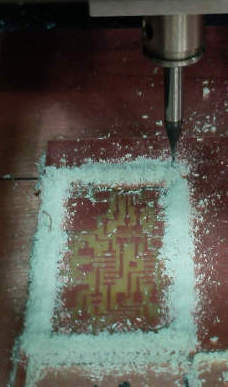
First, we have to use the 1/64" drill to mill the circuit on the copper layer. Then, we need to use the 1/32" drill to cut the board. The machine make three mills passes to get the cut.
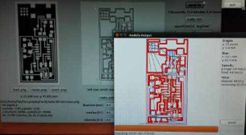
To mill with the Roland machine, we use the FabModules to introduce all the parameters that we need.
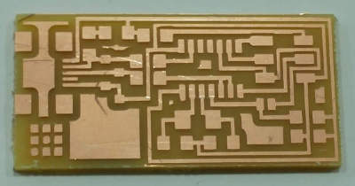
The ISP circuit ready to solder the components.
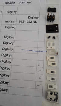
All the components to be solder on the board. To facilitate the collection of components and avoid confusion, we use a printed list in which we were sticking components.
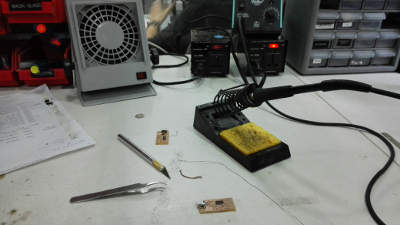
All we need to solder is a soldering iron, a tweezers and all the components to be soldering in the board.
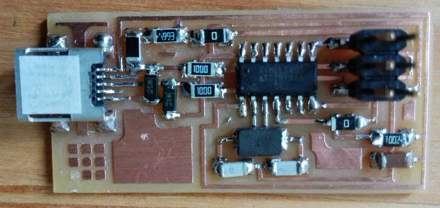
The ISP with all the components. Soldering the mini USB and the microcontroller was one of the most delicate operation of soldering, due to the tiny size of the components and the proximity of the pins.
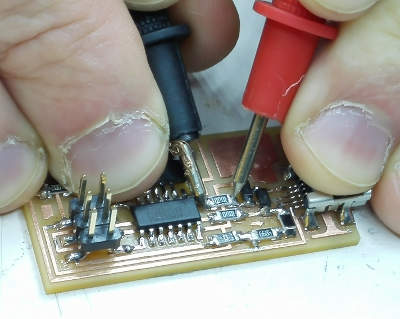
Once we have soldering all the components on the board, we have to test it with another ISP. Alert! Red light means that there are something wrong with the soldering, a short circuit. So we need to check all the solder joints, and correct the bad ones, if there. If we finally have a green light, we can programme our ISP. In my case, I had to fix one soldering before have a green light.
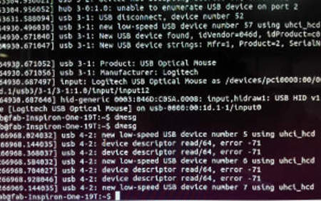
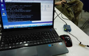
Once programmed with the Fab Lab firmware, the ISP was invisible to the computer. We get this error message with the command dmesg. So we need to check all the joints and all the components with the voltimeter. In the components organizers there was more than one components mixed, so we need to resolder at least two of them, so it's extremly recomendable to check that all the components are the correct ones and have the correct value.
After some hours of making checks, our classmate Jani, an electronics engineering expert, find the problem: a malfunction on a 100 Ohm resistor. Testing it with the voltimeter it give an a uncommon value, so the suspect was that the resistor was defective. I change it, and finally the computer detect the ISP. In Windows 8 OS, when we connect the ISP we get an error advise, but it supose to works properly.
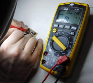
Our expert in electronics, Jani, making and exhaustive analysis of the circuit, first visually to check the solderings, and then with the voltimeter to check one by one all the components. It took almost a day to get to discover the circuit failure; in this case, only the experience and knowledge of an expert were able to find the fault.
Doing this excercise this week, we found a lot of differents problems. So we need to considerate some important steps for making a PCB:
- Be carefull manipullating your PCB, the copper layer could doesn't work if it suffer even a minimal scratch.
- When selecting the components, even if in the organizer are all the components marked, check it! In case of doubt, compare it with your classmates or ask the instructors.
- Before you start to soldering, read and follow the tutorial, there are a lot of useful instructions!
- Check the correct position of the components, some of them have to be correctly placed due to polarity, etc. If you don't do it, the circuit maybe doesn't work, or worst, you can burn your circuit. Desolder with braid it's not easy, so be sure you are soldering the correct component in a correct position. In any case you can use the hot air gun desoldering.
- Once all the components are soldered, make an exhaustive check to all the solderings, specially the tiny pins of the microcontroller and the mini USB: they have to make contact with the board, but don't have to be connected to each other. Also is recommendable to reflow the solder joints that look cold, they have to be bright. Finally, check that all the components are making contact with the soldering.
You can find the files to mill the helloISP44 PCB and the files tho programm it in the Fab Academy 2015 Electronics Production webpage.

Fab Academy 2015 website by Milena Orlandini is licensed under a Creative Commons Attribution-NonCommercial-ShareAlike 4.0 International License.
