
Group Assignment
"automate your machine. document the group project and your individual contribution".
Yes we can: we built a 4 axes CNC hot wire cutter! Amazing what you can do in two weeks with 8 motivated people. This link will take you to our common project documentation. Here I'll highlight my own contribution to the whole process in the cutting and assembling of the stages and designing the machine housing.
preparing cutsheets, cutting and assembling
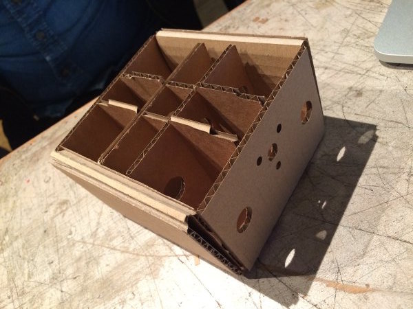
MIT's Nadya Peek prepared a cut file for a set of reconfigurable cardboard stages, that should be part of each machine. Joe and I took upon us the task of preparing these cut sheets, cutting the parts and assembling the four stages. This all sounds far more straightforward than it actually was, we suspect the files were tweaked to accelerate our learning experience :)
Before we ran the entire cut sheet we ran a few test cuts so that we could get our laser speed and power values right, also for the parts that need folding.
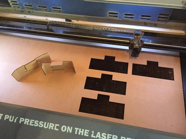 We then defined the settings for the epilog laser:
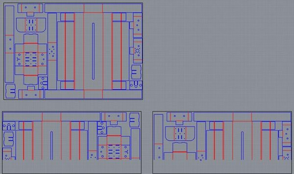
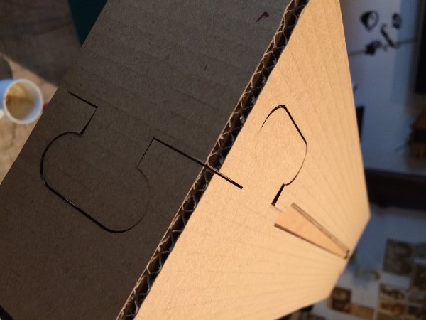
We soon found out that the cut sheet had to be divided into a two job cut as the body of the stage was larger than the laser bed. In Rhino we split the original cut sheet into two. The top sheet in the screenshot above is the size of the cardboard purchased and the bottom two are the size of the laser bed. Our plan was to insert the large piece of cardboard and cut it, then turning it around and cutting the other half. This wasn’t precise enough though, so we made two seperate parts that connect like a jigsaw puzzle:
While assembling the test body of the stage we noticed that some parts were a bit tight, so we took a few millimeters off in the cut file. While assembling the moving part within the main frame, two cardboard ‘flaps’ overlapped by 10 millimeters, so we reduced that size as well.
There were several other issues we encountered;
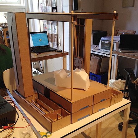
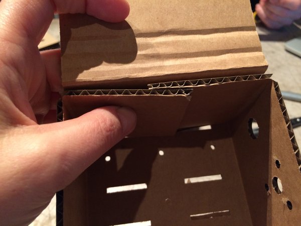
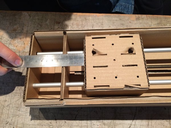
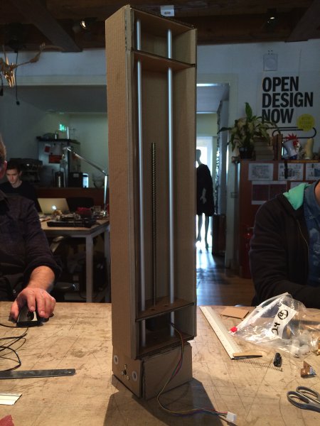
Unlike in the animated GIF, there are no holes for the rods to go through to the outside of the stage. We do want them to go through, because we found that the extra length of the rods can function as a connection between the horizontal and the vertical stages, like the picture below. This is why we added two holes into the top of the moving part of the horizontal stages.
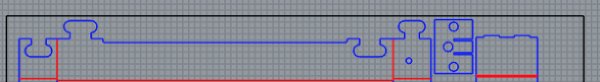
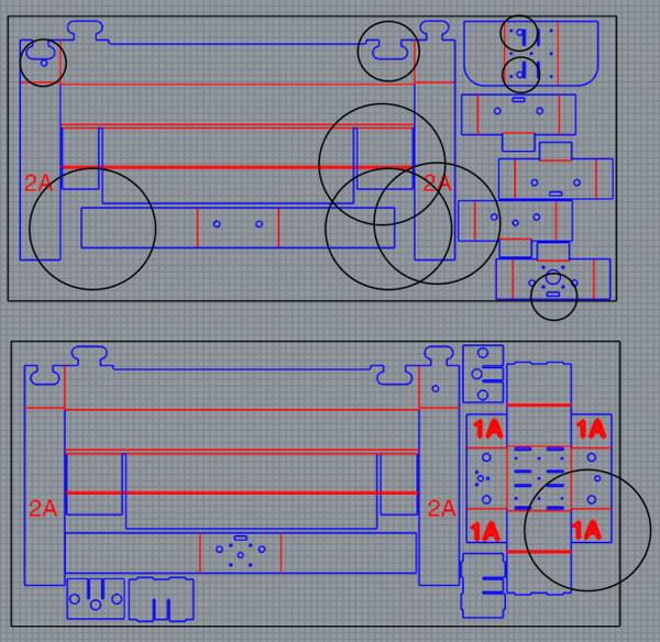
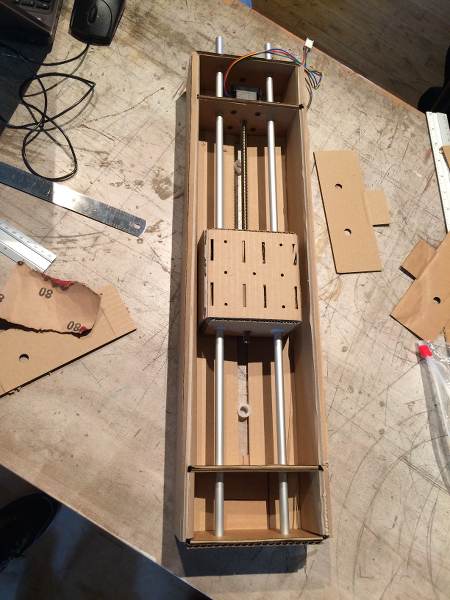
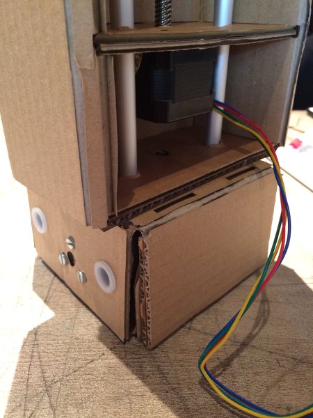
We also added additional holes in the cut files to accommodate 8 end switches, so we’ll have end stops on both sides of all axes. Finally, we adjusted the housing to accommodate the range of the servo motor, so that the moving part will actually hit the end stop. In this screenshot I highlighted the changes we made to the original sheet;
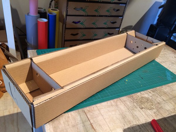
Now, let’s cut and build some stages!
Instead of the yellow glue, we tested the 3M Photo Mount as an adhesive to stick some of the cardboard flaps together. It dispensed evenly and worked quite well.
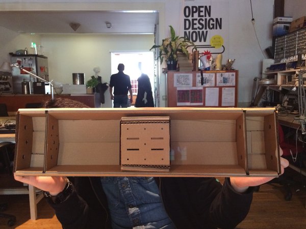
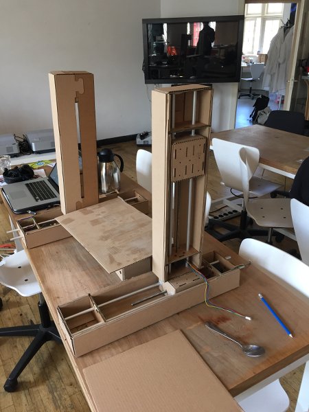
Now that the stages were finished, we were able to determine the size of the maximum cutting hight and length at 28cm. We then decided on the size of the bed: 28 x 56 cm, to allow for bigger-than-standard pieces of foam to be cut. But if the bed would be wider, the angle that can be cut will be smaller, so we kept the size like this:
X = 28, Z = 28, Y = 56
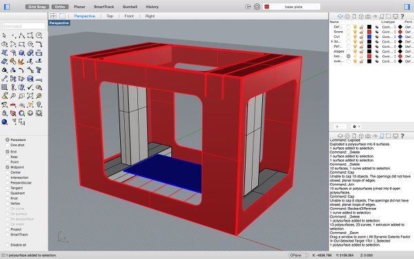
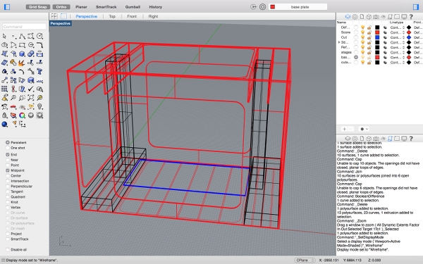
When designing the housing for the machine we need to take into account the height and size of the bed (how to raise and secure it) and how to secure the stages so they don’t move when the wire is stressed. We’re thinking of an Ultimaker-like construction but press-fit, that integrates a base that fixes the bottom stages and raises the bed, and also fixes the pillar-stages so that they can only move along one axis. We used the cut sheet to extrude the stages in Rhino 3D and design the box around it. Next up is designing all the parts including the joints to fasten the box. We bought a large sheet of 5mm plywood to cut the box with the shopbot later on.
The large part of my contribution ends here. Others have continued with and modified our design since then, also to accomodate the pulley system for the thread and the rails that guide the stages. I spent another two days at the lab helping out in cutting the plywood and assembling the final housing, and I did a lot of the early documentation on the project. A fascinating assignment!
Resources