
shirley niemans
week 11 output devices
Assignments
"add an output device to a microcontroller board you've designed and program it to do something".
..................................................................................................................................................................................
Choosing, designing, milling
April 16 / In my final project, I will most likely use an LED array and a speaker as output devices. For this week, I'll try to make a board with a speaker to see which tones I can generate with a simple circuit, and what difference various types of speakers make.
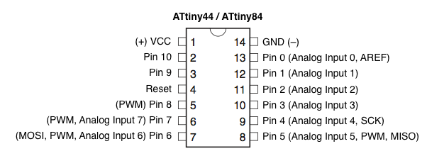
April 19 / I designed a board that allows a 12V or 9V power supply to connect to the speaker and a 5V regulator that provides VCC to the rest of the board. Then a transistor and a 4 pin header to which I can attach (alternately) 3 kinds of speakers and a piezo. This time I decided to use the ATtiny44 microcontroller, bacause it has quite a few more pins and a bit more memory I can use, and I have no idea how big my sketch is going to be. Most likely I'll need this IC for my final project so I'll practice with it.
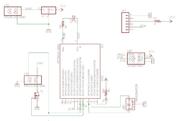
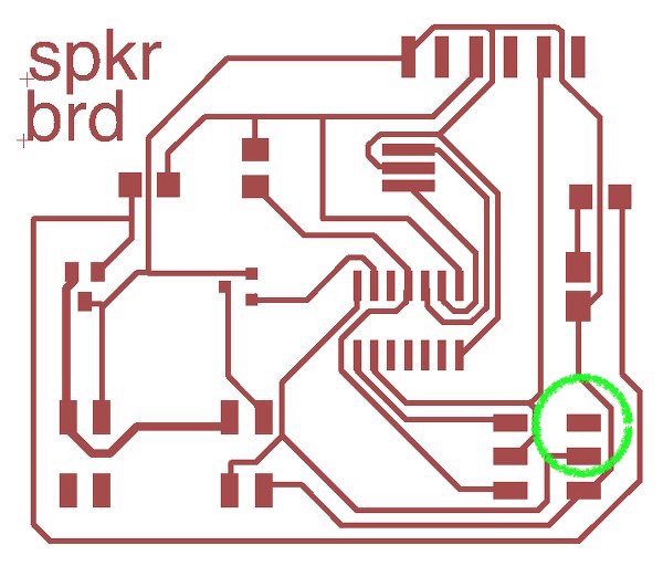
I didn't forget to add the border to both files and milling of the board went without problems, however I did miss routing the VCC wire to the ISP header in my layout, making it impossible to burn the bootloader. Nothing a jumper couldn't solve, but I was very annoyed with myself and made a mental note to quadruple check next time. This week I also came across some very useful sparkfun tutorials on the workflow of circuit board layout in Eagle.
 ..................................................................................................................................................................................
Programming the board
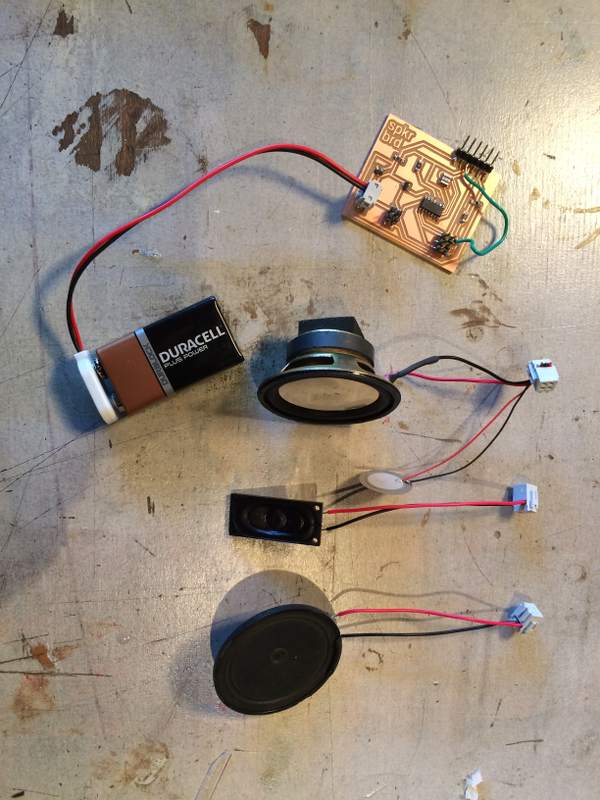
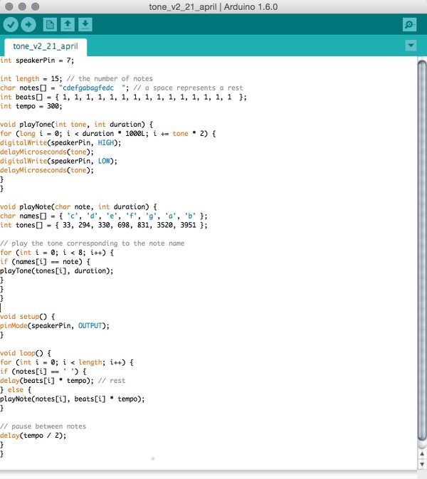
 Apr 20 / After soldering and assembling all the speakers and a 9V battery, it was time to code. I'd already come across the Arduino tone() command that generates a square wave of a specified frequency on a pin to which a speaker is connected, to play tones of various duration. Browsing through previous fabacademy projects to see what others have done, I came across the code that Emma Pareschi initially used to generate tones through the attiny44.
Since the first tone that came out of the big speaker scared the living daylights out of me (and the people around me) I used the pitches.h library in Arduino (see the long list below here) to generate tones representing the whole frequency range, to hear what they sound like and which frequencies might generate tones that would be better fitting to use in a children's toy.
Apr 20 / After soldering and assembling all the speakers and a 9V battery, it was time to code. I'd already come across the Arduino tone() command that generates a square wave of a specified frequency on a pin to which a speaker is connected, to play tones of various duration. Browsing through previous fabacademy projects to see what others have done, I came across the code that Emma Pareschi initially used to generate tones through the attiny44.
Since the first tone that came out of the big speaker scared the living daylights out of me (and the people around me) I used the pitches.h library in Arduino (see the long list below here) to generate tones representing the whole frequency range, to hear what they sound like and which frequencies might generate tones that would be better fitting to use in a children's toy.
I soon found out that, roughly speaking, tones below 100 hertz and above a 1000 hertz are either unpleasant or more vibration than sound. I'd like to continue that research more accurately later on. Also, I'd like to find out how to make use of the PWM functionality to control the volume by changing Pulse Width.
Somewhere in the process of programming and reprogramming, I connected the battery to the 4 pin header the wrong way around, which broke the regulator on the board. The speaker now will only play when connected to VCC either through the ISP's USB. Luckily I can still plug and play that way so the assignment is complete for now. Check out the video below to hear the difference in sound between notes down the frequency scale, and the various speakers.
ATtiny44 with three speakers from shirley niemans on Vimeo.
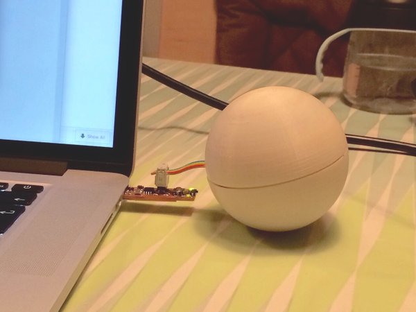
After I knew the size of my board and the components, I 3D printed two balls that screw together. It's an existing design which I plan to modify for prototyping purposes. I stuffed the speaker, the board and the ISP connector inside, closed it more or less and tried out what it sounded like then: Muffled, definitely better sounding for the volume it's producing. And a bonus finding; The 1000hz+ tones make the material vibrate, which has a really nice feel to it.
Some notes on workflow
- - Place a diode or a switch at the output of the regulator to prevent current flowing back into it and killing your component
- - Use fat traces not only for (high) power, but also for ground
- - Quadruple check for airwires in your board layout
Resources