
Assignments
"measure something: add a sensor to a microcontroller board that you've designed and read it".
Choosing a sensor
April 10 / After the local lecture on input devices by Emma Pareschi, I decided that - with my final project in mind - I'd like to test three sensors: The Hall Effect sensor (magnetic field detection), Step Response and - most of all - the 3D Accelerometer. After doing some research on all three sensors and how to wire them, I found that the accelerometer would be quite difficult to get working and even to solder, due to its microscopic size, within a few days. Bearing in mind the fact that I'm trying to catch up on earlier assignments, I decided not to go for the ultimate challenge this week. I'll make a circuit board using the Attiny45 microprocessor and a hall effect sensor. That way at least I can test whether this sensor would be good to use for triggering light or sound when the temari balls (see final project proposal) are (almost) touching. Perhaps I'll add the possibility for step response, since that would also be a way for the balls to interact with eachother. Also, it takes up no extra space on the board so I have time left....
Designing and milling the board
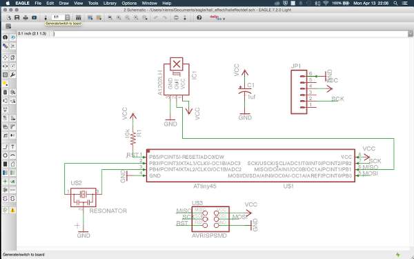
April 13 / There's no time left :) I spent today designing and milling the board and trying to repare my ISP, which after a final check by Zaerc we now believe to be deceased, so I'll have to borrow one to burn the bootloader to the microcontroller on my new board, and make a new one later. Along with the hall effect sensor, I placed a resonator on the board to ensure stable serial communication.
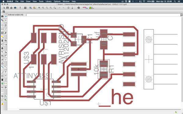
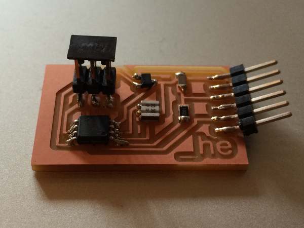
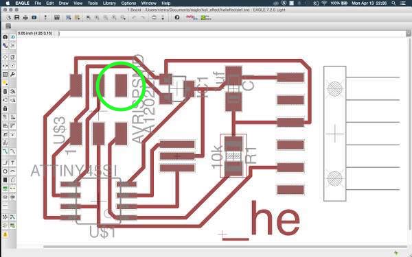
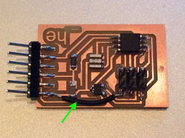
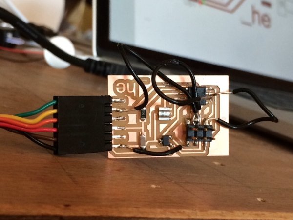
It's been several weeks since the last time I milled a circuit board, and I forgot to add a black border around the .png file for the board cut out. I added a 40 pixel border only after I had milled the traces, thereby enlarging the cut file relative to the trace file. I tried to make up for this by moving the x and y values of the Modela by -1.5 mm. This turned out to be slightly too much, but just okay for the board to still function and the traces to stay whole. This is the _he (hall effect) board:
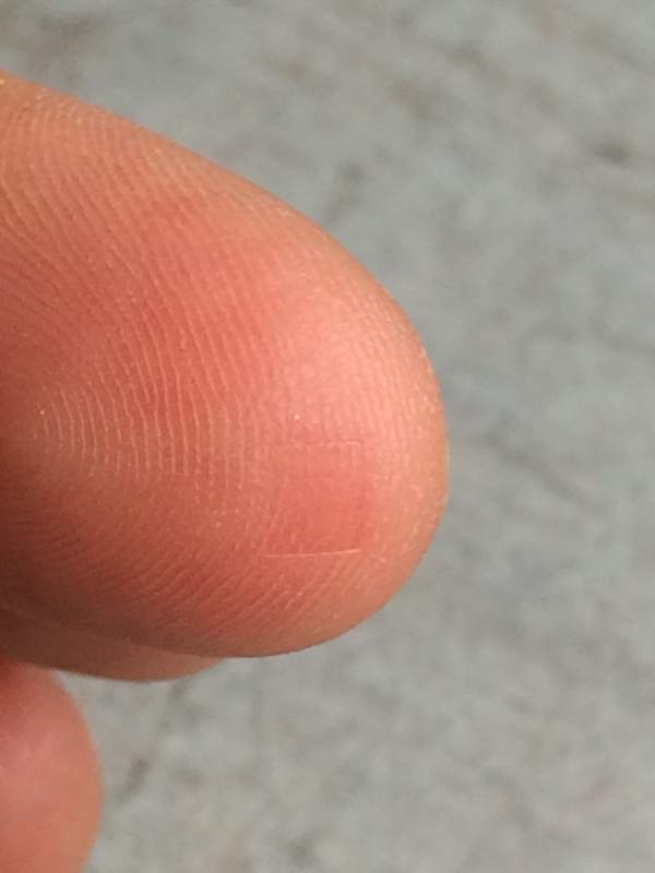
This is the burn scar you'll get when pressing down a red hot resonater.
Apr 14 / Then I connected:
" avrdude: initialization failed, rc=-1 Double check connections and try again, or use -F to override this check."
I encountered this error before and I know that the problem is that the computer does not recognize the chip correctly. This could have many causes. I double checked all solder connections, tried a different ISP, connected a usb2 hub in between the laptop and the ISP (sometimes there's compatibility issues with my usb3 port), and eventually even replaced the microchip on the board. When the latter didn't fix it, the problem could only be in the board layout. Emma found it: one headerpin didn't have any connection. How obvious when I look at it now. In the Eagle schematic I rewired the ground and the pin, and then routed it in the board layout. On the actual _he board, I fixed the connection with a jumper cable. We were then able to burn the bootloader to the microchip.
 ..................................................................................................................................................................................
Programming the board and reading the sensor
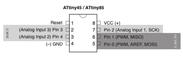
The hall effect sensor is connected to pin 1 (MISO) on the ATTINY45. I decided to go for Arduino coding since I've done that a bit in the past and learning C seems too ambitious for me right now, timewise. Unfortunately, that didn't mean that I got the assignment finished in time - it's 2:37 at night now on the evening before presentations and I'm really stuck. Even after intensive researching I'm unsure whether I should set the Attiny internal pull up resistor for the hallPin (MISO, 1), to do the analogRead. Also, I haven't been able to get serial communication going. I keep getting the error: 'Serial' was not declared in this scope. On this Instructables page I found a tutorial on how to use the SoftwareSerial library in Arduino, so I tried that out with this code:
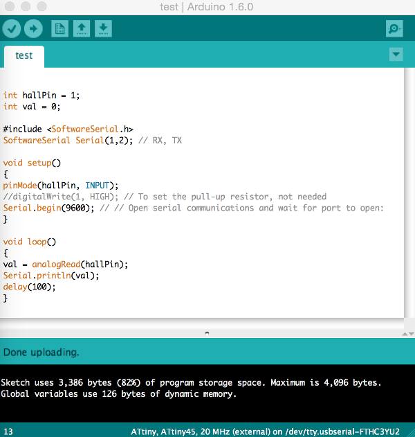
This does produce a contant output flow of 852 to 858 in the serial monitor, but it doesn't change when I hold a magnet near to the hall effect sensor.
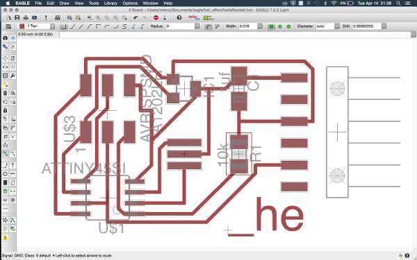
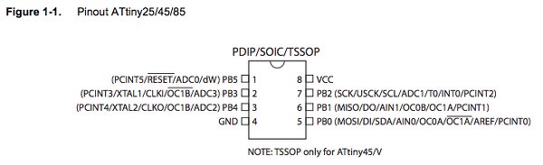
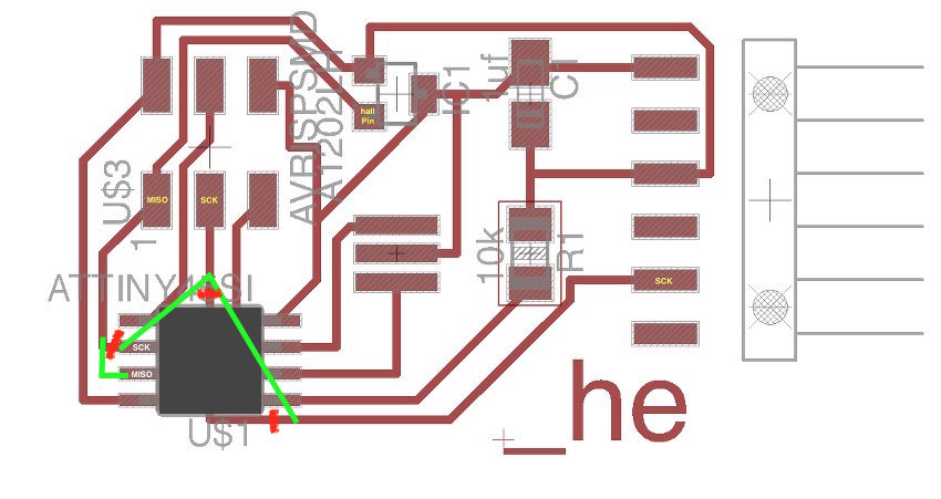
I just found out why; the MISO and hallPin are on pin 1 of the ATtiny, which doesn't have an ADC converter (as I could have seen in the pinout above), and so cannot do the analogRead. Just connecting the hallEffect sensor to another ADC pin isn't possible, since those have been taken by the resonator. After discussing with Zaerc I'm going to try to switch the SCK and MOSI by cutting some copper traces and adding some more jumpers to the board, so I can read and play with the sensor data. I annotated the Eagle board file to understand what I was doing (the white letters represent the new pin names) and then cut the traces (red) and soldered the jumpers (green) on.
*UPDATE*
June 26 / I left the assignment for what it was when the fix mentioned above here didn't resolve the problems I was experiencing, thinking I'd get back to it with a fresh mind later on. As it happens, I didn't get back to the hall effect sensor, but I did experiment extensively with an accelerometer, which I read in various contexts (python, terminal, serial monitor) in week 14 and in my final project.
Next I created a new set of design rules in Eagle. Based on the 1/64th (0.015625) inch tool size that we use to mill the traces on the Modela I decided to set the minimum clearance to 16mil. I also decided to use this for the minimum trace width, although this could well be smaller.