
Assignments
"redraw the echo hello-world board, add (at least) a button and LED (with current-limiting resistor) check the design rules, and make it. extra credit: simulate its operation".
The assignment of this week wasn't necessarily a creative one, but attempting to solve the puzzle of adding and connecting components in an electronic circuit felt pretty creative at some points. ..................................................................................................................................................................................
Redrawing the helloEcho board
March 5 / Emma Pareschi gave us a 4 hour super interesting electronics design lecture. For designing PCBs I downloaded Eagle, a freeware Easily Applicable Graphical Layout Editor that I heard good stories about. The first step in learning how to do design one is redrawing an existing PCB, in our case the 'echo hello world board'. I began by looking up the right components in the parts libraries that come with Eagle, and the two libraries provided by Neil Gerschenfeld and the Fab organisation. It's important to find just the right component - the smd-kind instead of through-hole, the right value and size but also the right make, because they generate a 'footprint' for each component on which you will solder your actual parts later on. By adding and connecting components in an Eagle schematic, the program generates very exact 'footprints' and traces that can be milled in copper to make the board on which you will solder the actual parts. In assembling the correct components from various libraries, I checked in the Fab inventory whether the parts were actually there. I also Googled types to see an image (what is an XTAL and what does it look like) to get some clues as to which resistor, capacitor, microcontroller I should add.
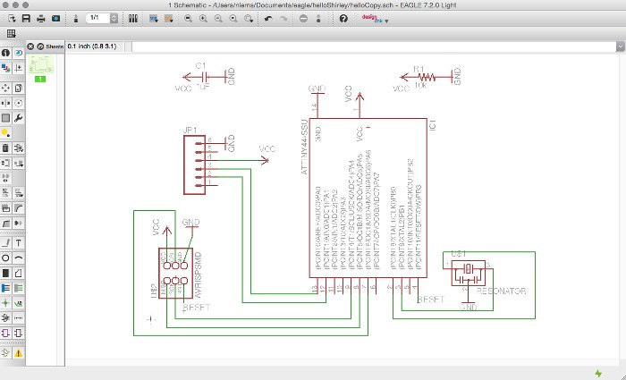
Connecting the dots
March 6 / After assembling components, they needed to be connected together within the schematic to form a functional circuit. After drawing many wires (called 'nets') by hand, I realized that it works much faster when you give the pin of one component the exact same name as the pin, wire, component you want to connect it to. This creates a 'link', an automatic connection and saves a lot of space. On the other hand - as I will talk about later - sometimes it's easier to understand the logic and the rules involved with components working together when you see the actual connections. Eagle has an 'electronic rules check' (ERC) that will render possible errors and point out the place in your schematic where they arelocated, which makes it easy to correct them.
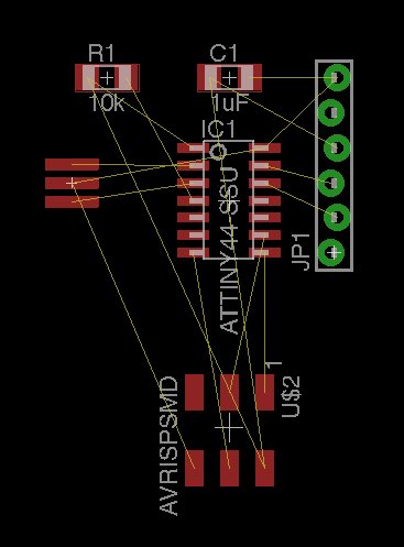
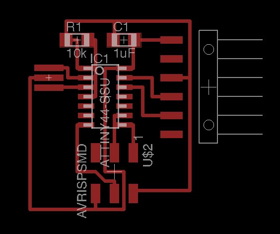
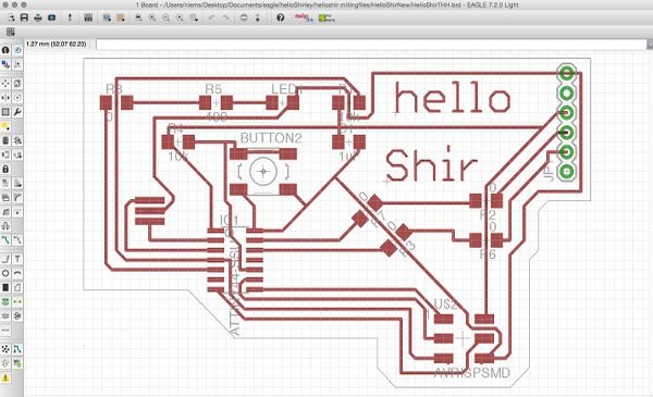
With all components connected in the right way, it's time to arrange them on the Eagle board and design the traces. Since the objective is to copy the helloEcho board, I will try to make it exactly like the original. When you switch to board view in Eagle, all components are clustered together outside the board, and you must manually move them in place, then route the traces from one component to the other. I liked the process and managed to resemble the original board quite well.
 ..................................................................................................................................................................................
Adding components to the helloEcho board
.png)
March 9 / My goal for this part of the assignment was to add two buttons and two LEDs to the circuit. The two buttons seemed like a nice challenge for the programming assignment later on. Adding the components to the Eagle schematic was straightforward, but adding the extra components to the helloEcho layout made it very hard to find ways to route the new traces. I tried many paths, got stuck with all of them and then started using the autorouter. When I found that correcting autorouter took just as much time, I went back to manual routing. Since I didn't manage either way, I decided to add only one led and one button and - I must admit - several 0 Ohm resistor jumps.
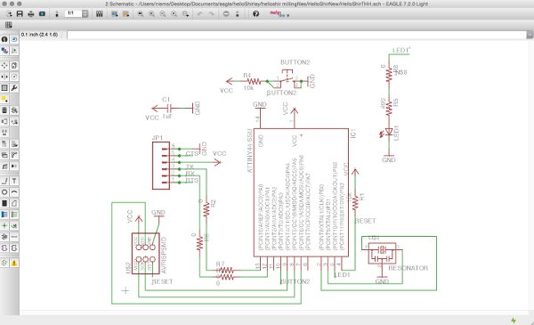
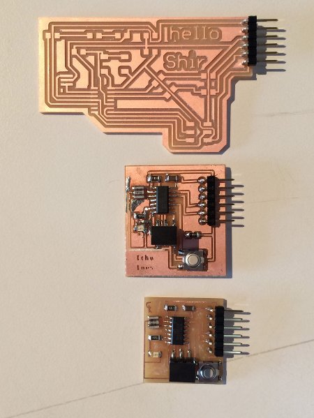
It all resulted in a circuit board layout that turned out to be HUGE when milled and compared to some of the other boards that were done in my class:
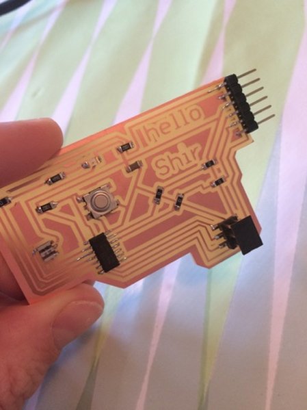
After soldering, it was time to test the board. Apparently, the round holes that were supposed to be milled beneath the 6-pin header were in a layer that I forgot to turn on when making the milling files. I managed to solder the pins to the correct paths though, but the connection might be less strong.
..................................................................................................................................................................................Some important notes!
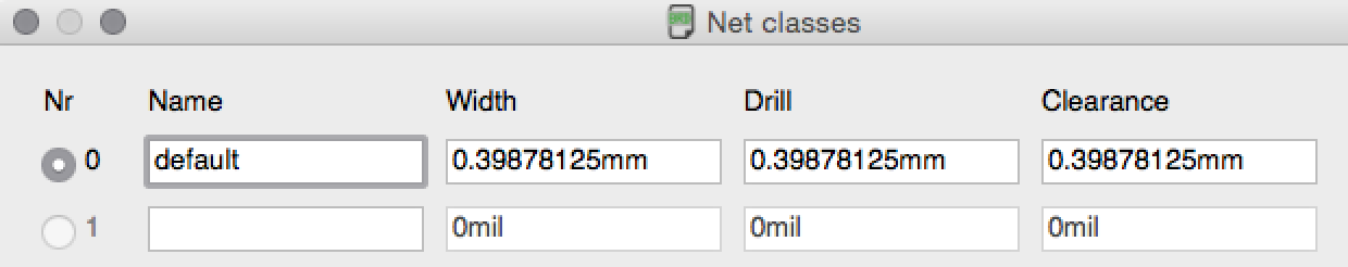
In order for the Modela to be able to mill your board, you need to tweak some setting in Eagle. First of all, in board view, go to edit>net classes. Here you can enter the size of the tool you are using. The tool we use to cut the trance on the Roland Modela is 1/64th (0.015625) inch tool size, which translates into about 0.4mm:
Then, in board view, go to edit>design rules and set the clearance to 0.16set the minimum clearance to 16mil. You could also do this for the minimum trace width (under the 'sizes' tab in design rules), but I don't think it's necessary and it will make routing more difficult.
Resources