Composites
This weeks class of Fab Academy 2015 was about working with composite materials. We learned about plastics and the creation of larger structures.
To quote Prof Niel Gershenfeld:
"I'll come back to safety but stay away from glass and carbon fiber"Design
What I hope to achieve is a Low Poly Bathtub created from a solid polygon that is extruded and then separated into distinct panels. These panels will be Milled into wooden panels that can be used in the molding and casting week to make a low poly bathtub.
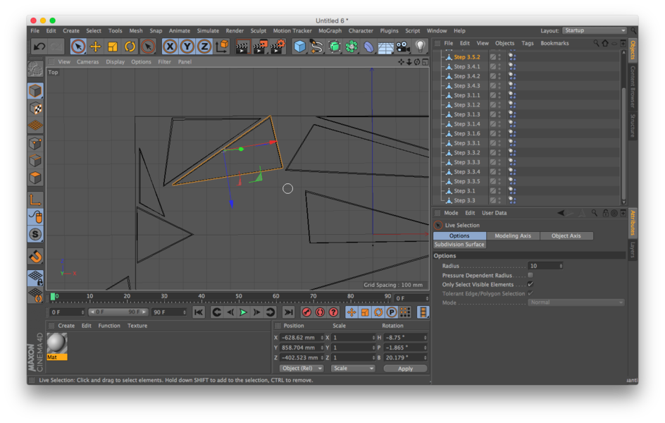
I tried to do this project in Antimony, but the project depends on Decimation which doesn’t exists yet and I don’t possess the skill to script it myself. So I fell back on an old reliable, Cinema 4D because I want to experiment with using the animation functions to drop all my pieces to the ground plane for the milling Process.
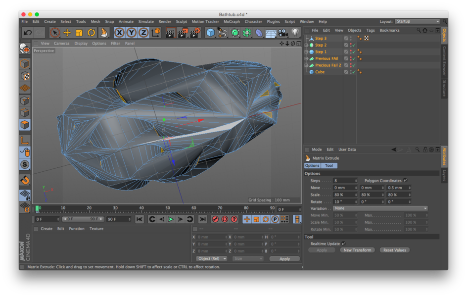
Step 1
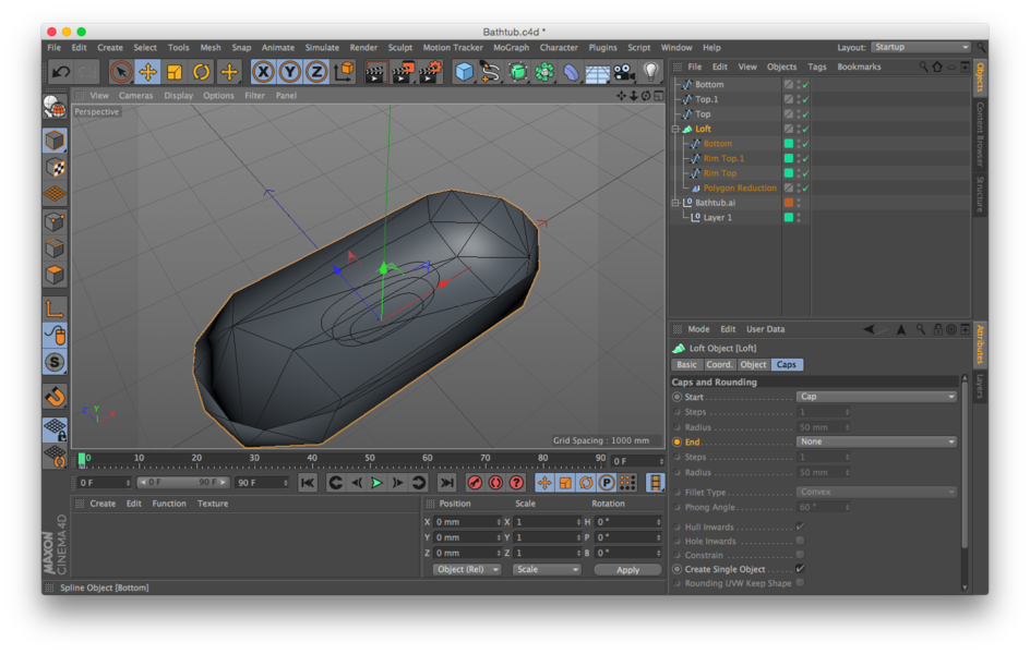
After evaluating several data sheets for bathtub dimensions and measuring the few I have access to I came to the dimensions. 66cm x 180cm x 40cm. I tried designing pollens for a Loft Nurb in Illustrator, but I didn’t like the curves. I retried them in iDraw, still not perfect. I finally bit the bullet and learned how to create polylines in Cinema 4D. This was fail #1.
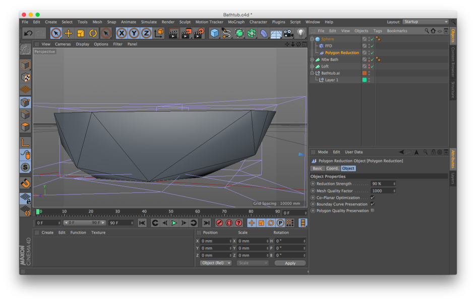
While this rendered the overall shape I wanted when I applied the polygon reduction (decimation) the shapes generated were not what I needed. I scrapped version one and went back to the drawing board and remade the polylines with anima curves, repeated the process of creating a loft nurb followed with 93% decimation and it still looked wrong.
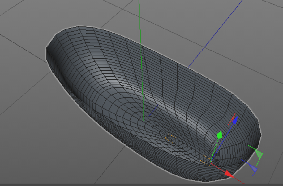
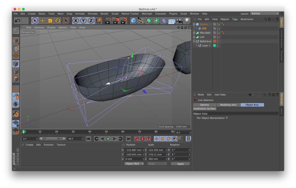
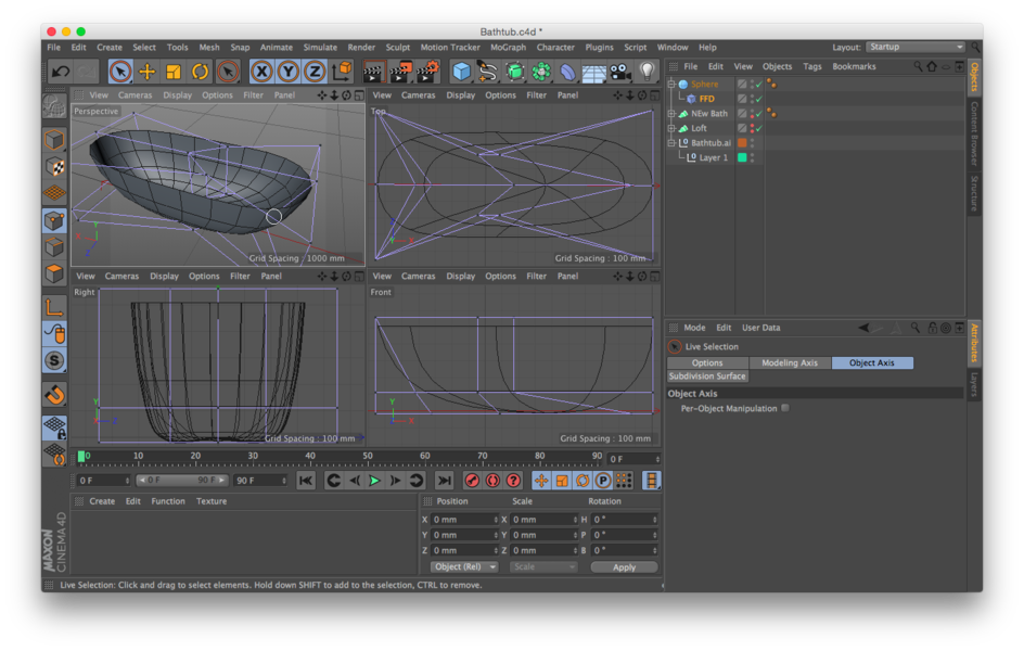
The next attempt involved a Hemisphere and use a FFM deformation to achieve the object. This finally resulted in the desired shape. It’s ironic how often the FFM deformation is the solution and how rarely it is used in the first attempt.
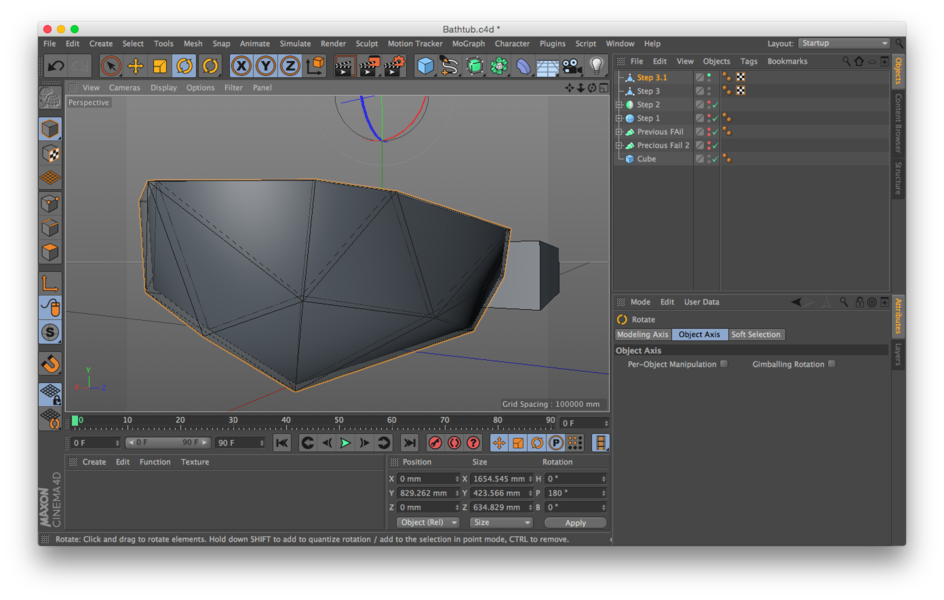
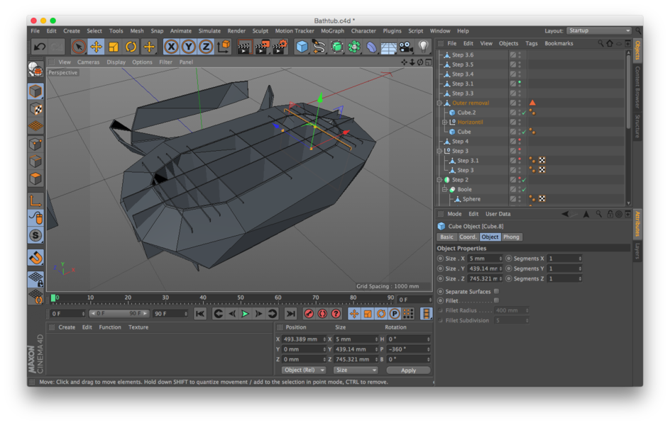
Step 2
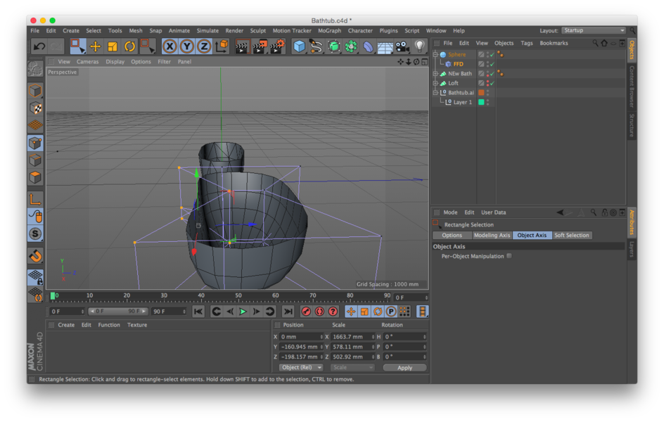
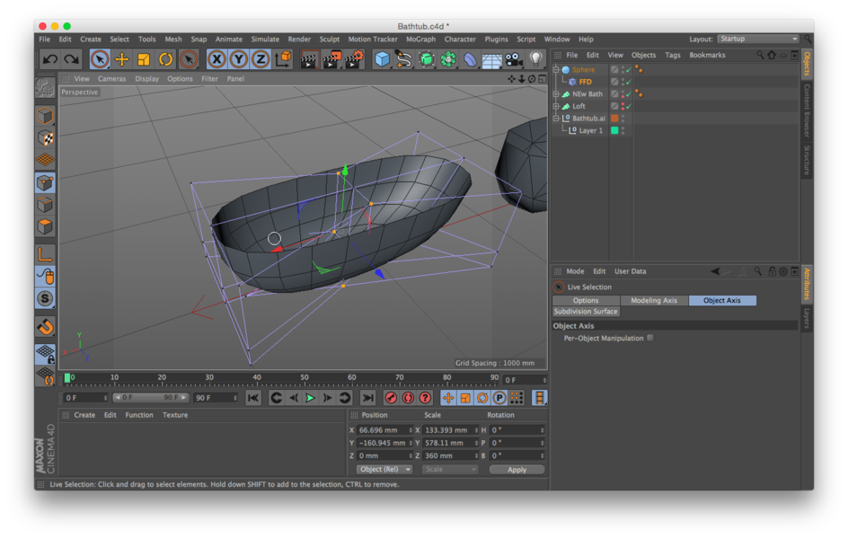
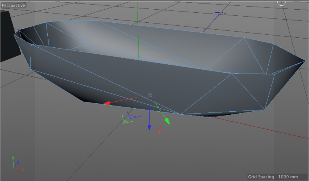
Once the low poly decimation looked great the next step was to mirror it over the median plane to provide an aesthetic quality that is relational to the human anatomy it will enclose. The FFM Deformed hemisphere provided a model that would function well with this line of symmetry in mind and only three points needed to be moved to make this work. The two halves welded together create the new shell.
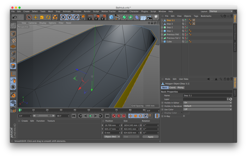
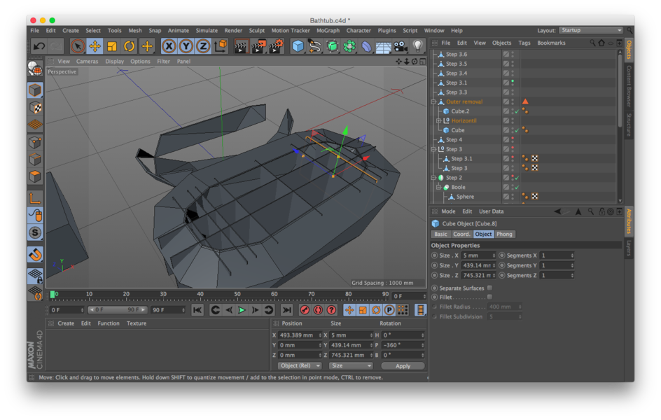
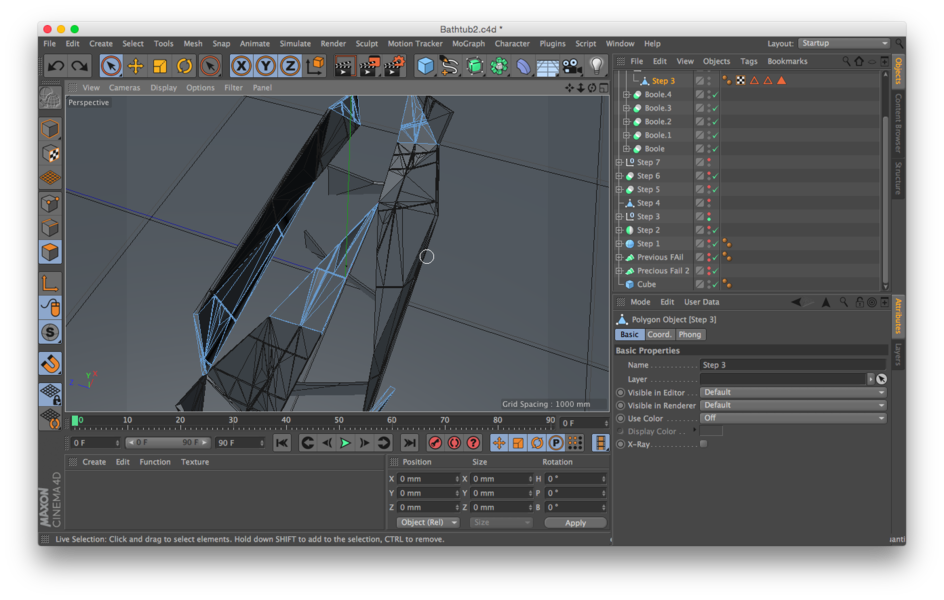
Step 3
The shell next extruded out 15mm (the width of the wood used for milling) using a Smooth Shift to create the width. Interestingly, the normals on the inner shell aligned distal (away from the center) and needed reversed proximal before the inner and outer shells could be unified into a manifold object.
Step 4,5,6
In order to simplify construction I passed a whole day designing an interlocking support structure and subtracting 5mm troughs from the panels in order that they slide in to place. After three separate attempts with multiple errors that required hand correction the realization struck that without a 5.2 axes milling head this was going to be impossible. I abandoned these explorations substituting the idea of planar Tensegrity (Like the sticks, but with planes.) While a lot of time was spent failing, the realization of the limits of the mill we are using was worth while. It’s easy to see why a 5.2 axis mill costs 100,000$.
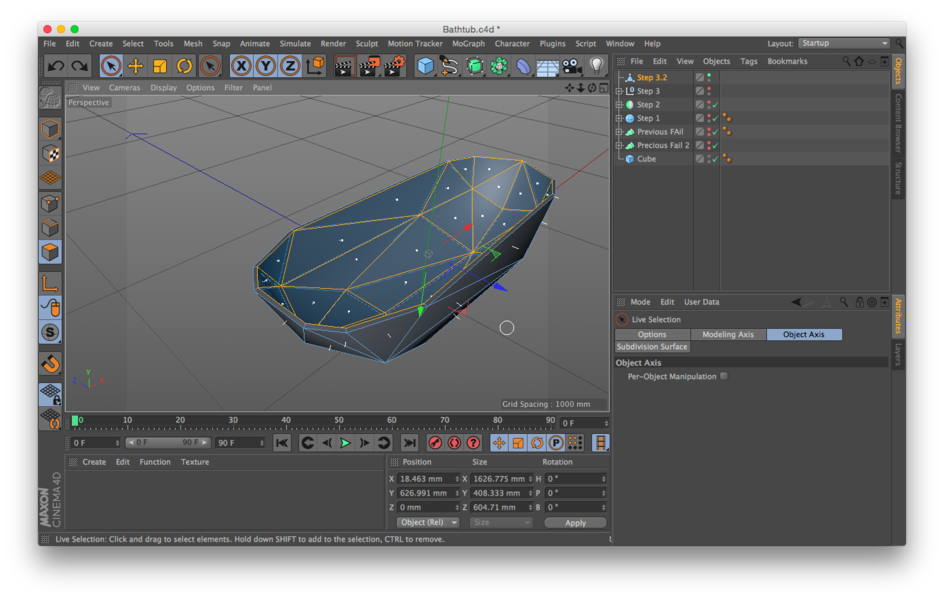
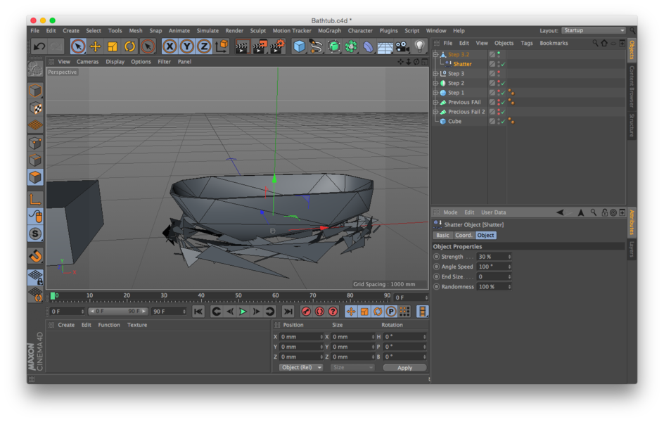
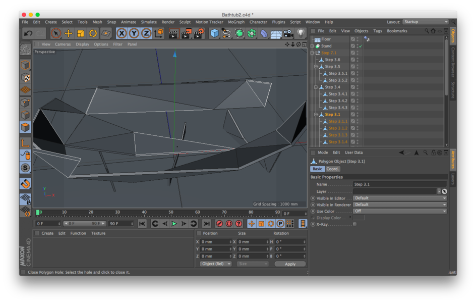
Step 7
All of the pieces needed to be separated into individual items. Three tries to make the Xplode slice the model via a voronoi slicing tied to the nodes resulted in no success. To hand slice the model six copies were used to ensure that no nodes or vertices were shared between models. It was time intensive to do it by hand but the result was ok as all the panels were in separate groups.
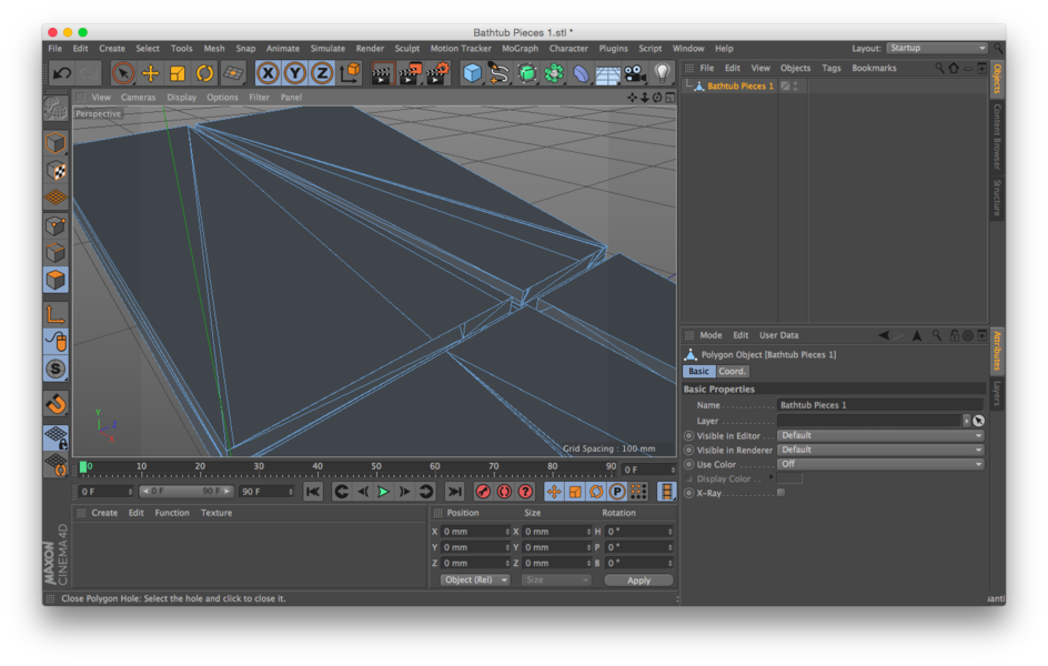
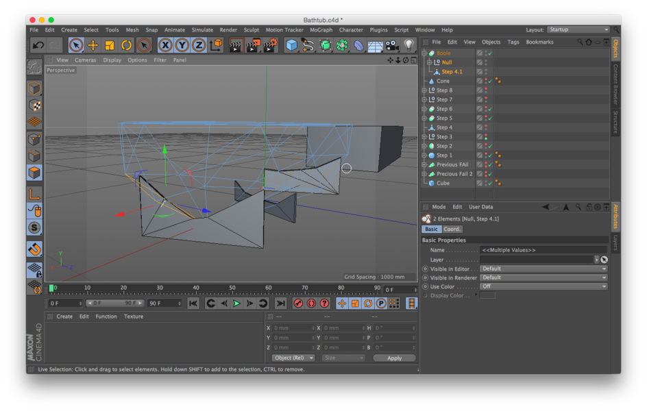
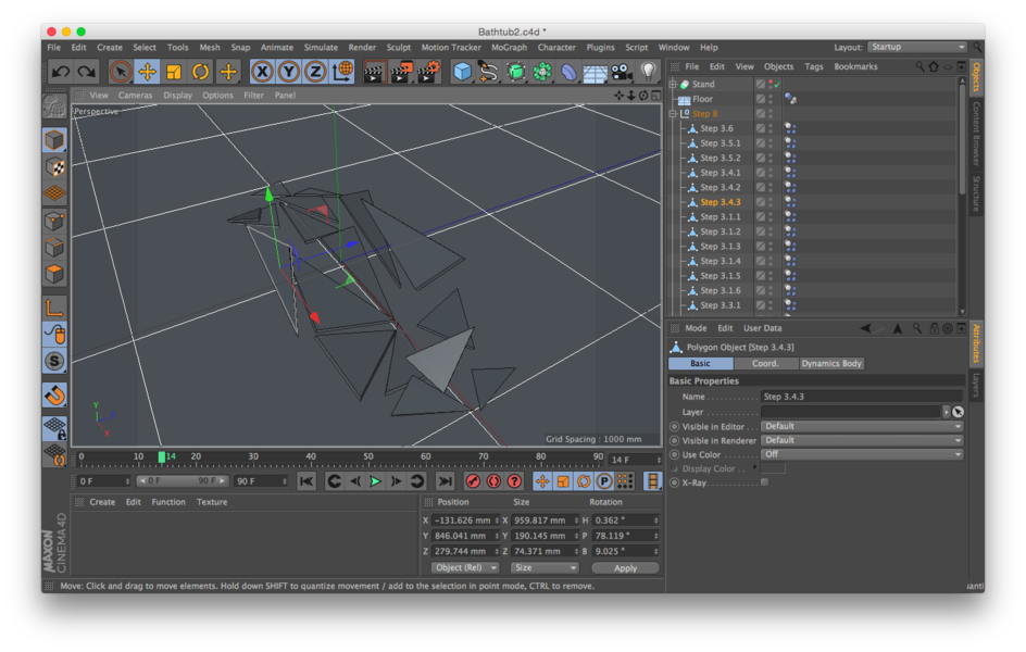
Step 8
When I separated the pieces before I made sure that no group shared a similar edge. This allows a model optimization in MeshLab that will give us watertight objects that we can then animate to drop to the floor. This is not a mandatory process but optimization in Cinema 4D only goes so far. With these grouped objects I ran a Polygon Groups to Objects command and ended up with each panel on its own level. Then the fun began when a floor was added and Rigid Body Collider tags added to all the objects. It took a few tries and repositioning of pieces to get the gravity correct but eventually all the pieces were ready.
Step 9
I arranged all the pieces into two sheets of 2m x 1m boards and double checked the spacing for the milling machine. All is ready to mill.
Production
In order to expiriment and determine the best amount of knit and burlap infill I ran a series or samples using different amounts of burlap.
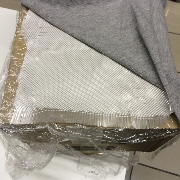
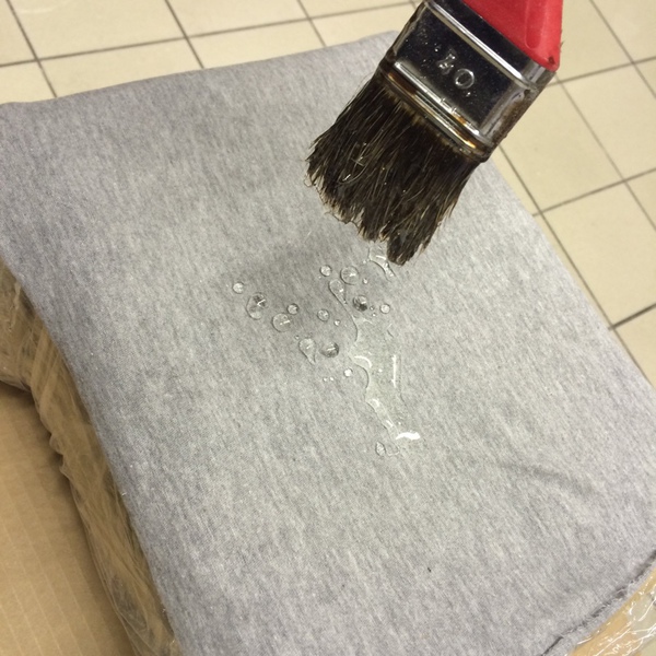
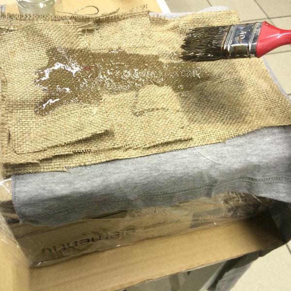
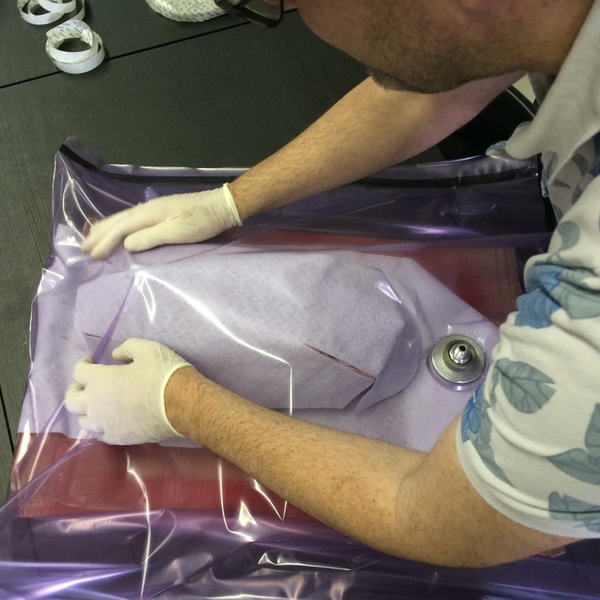
I created a sandwhich of fiber glass cloth, jersey knit, burlap, jersy knit, fiber glass cloth. I applied the composite material in a 1:2 ratio in the middle and top of the mixture.
I vacumed bagged it on a box and after an hour I let it cure.
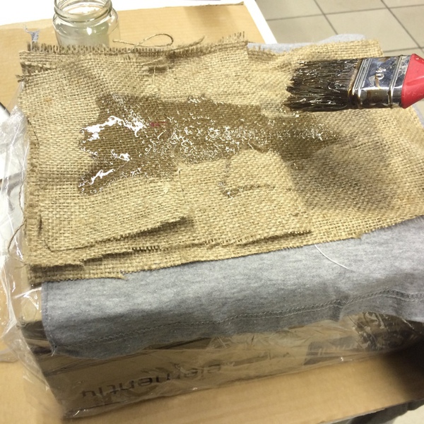
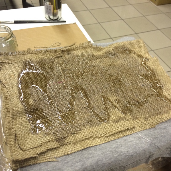
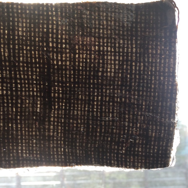
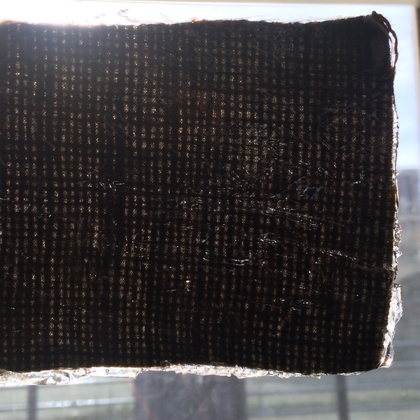
Twelve hours later I had to leave, but it seemed solid. Unfortunately it was not completely cured and was crushed in my bag. Lesson learned, let it cure. While this was a failure due to not letting it cure long enough I learned which amount of burlap I would need to make it structurally sound, visibly closed (a sinlgle layer of burlap transmits a cheakerboard of light) and the amount of color change that the final material will present. (Tt's always wet.)
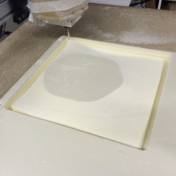
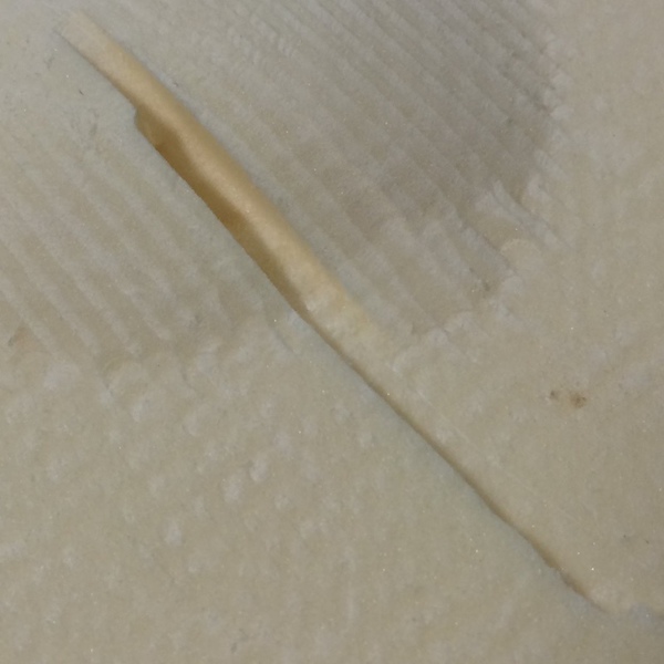
After a few attempts at milling foam on the Linux CNC and seeing the struggles of my Lab mates with the CNC mill in 3D as well I realized that it was going to take more than a week to mill all the pieces. I've redesigned everything to recut on the Laser cutter but I remain without enough time to complete the project.
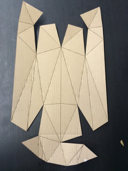
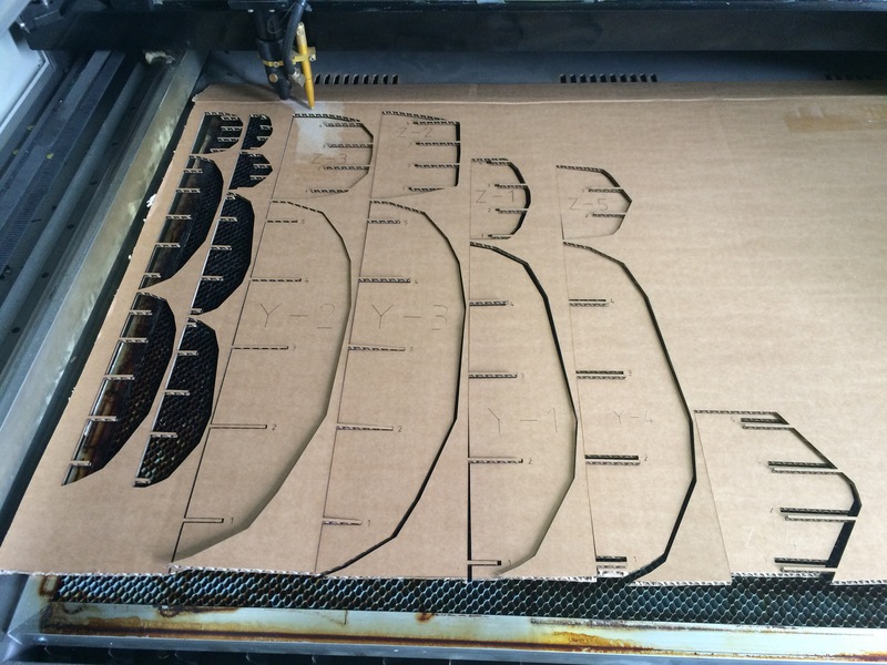
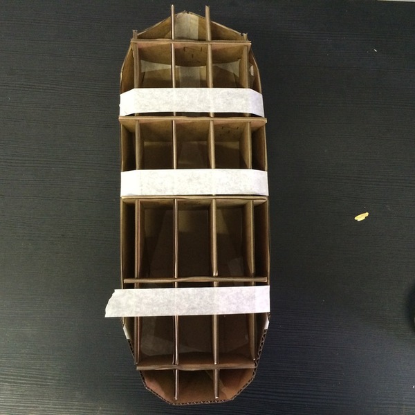
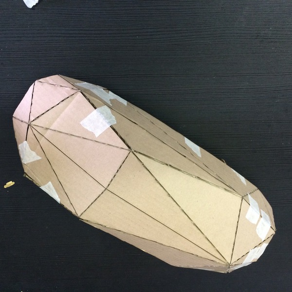
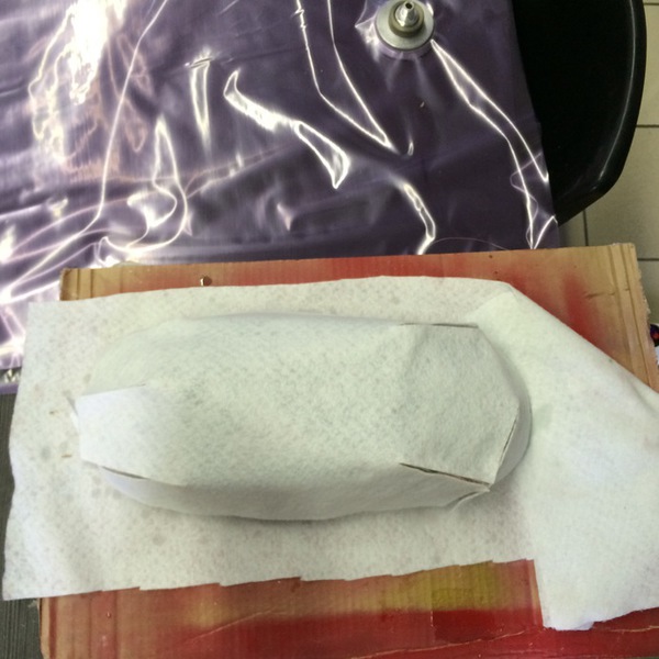
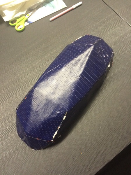
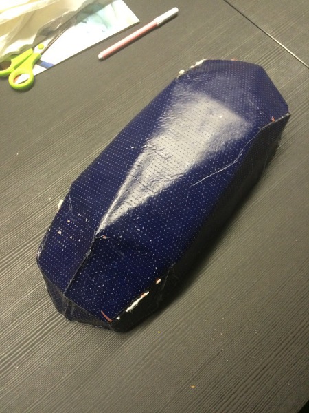
So three weeks later I am using a new approach. This is 1/6 scale of the bathtub I want to make. I used the flattned pieces from Cinema 4D to create a flat layout with Illustrator (Update: I just looked at the new 123D Make and there is the new ability to slice a flat exterior. This is a much better way.) I laser cut the exterior and created a support structure with 123D make for the interior. Half an hour later the tape has held and the structure is ready.
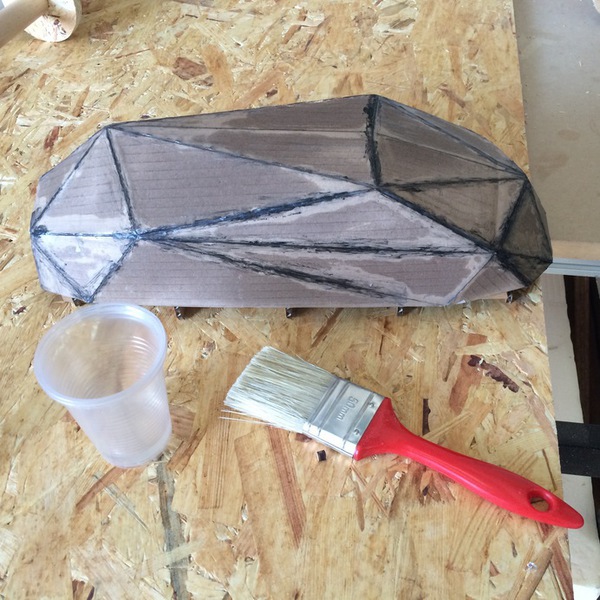
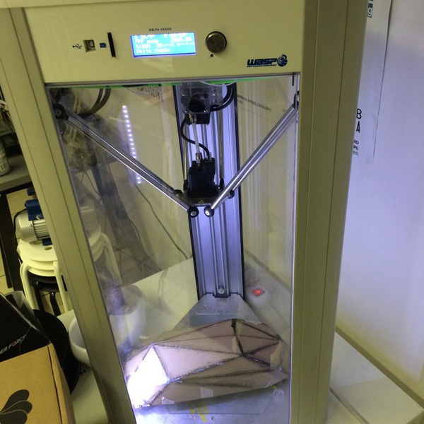
The gaps in the seams were sealed with three coats of glue, after drying I applied three coats of release to the structure. The heated bed of the 3D printer makes a great curing space that has speed up the time between coats signifigantly.
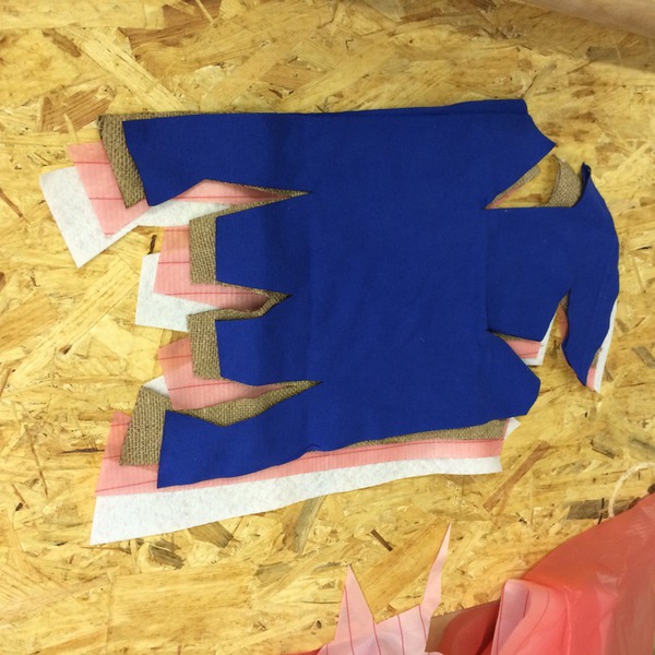
All Six layers; Jersey, Burlap, Jersey, Release, Fiber Glass, Felt were cut on the laser cutter using pattern making techniques to augment size in progresive layers. The remainder of the t-shirt was given to the awesome Laura of OpenSourceHardware.it who was headed to the beach. I tested the fit and all went well.

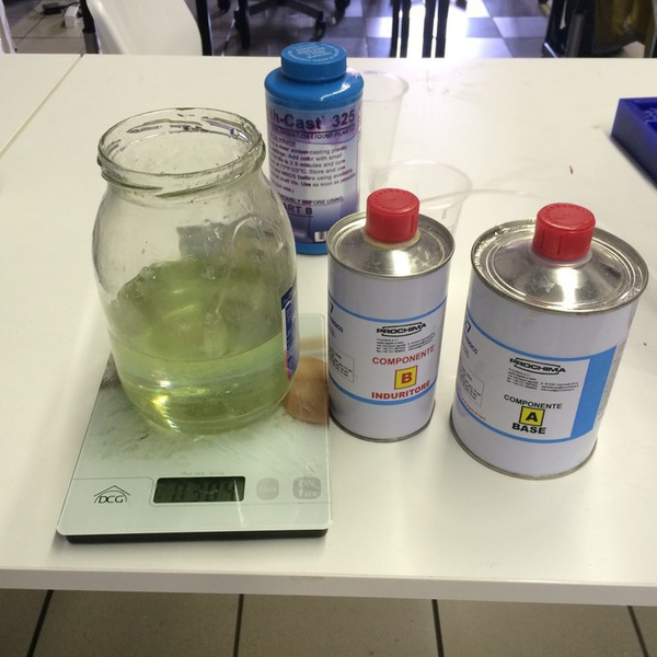
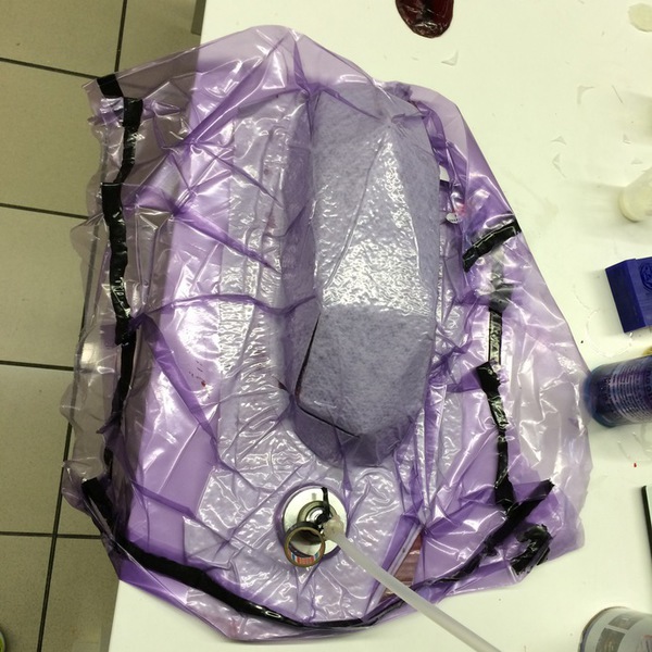
After reading the MSDS and watching the instructional video I mixed the resin and layed each layer up. The burlap was particularly difficult, but I survived and only had to make more resin once. I didn't add enough creased darts to the bag, but fiore helped me get it ready.
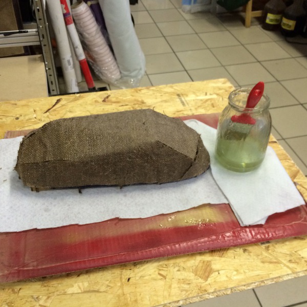
Vacuum was applied for three hours and the structure was left over night. I am removing the structure now, the internal supports were not close enough and the model warped under the pressure of the vacuum. Removing the release and felt was difficult but the vacuum would have worked if the supports had held.
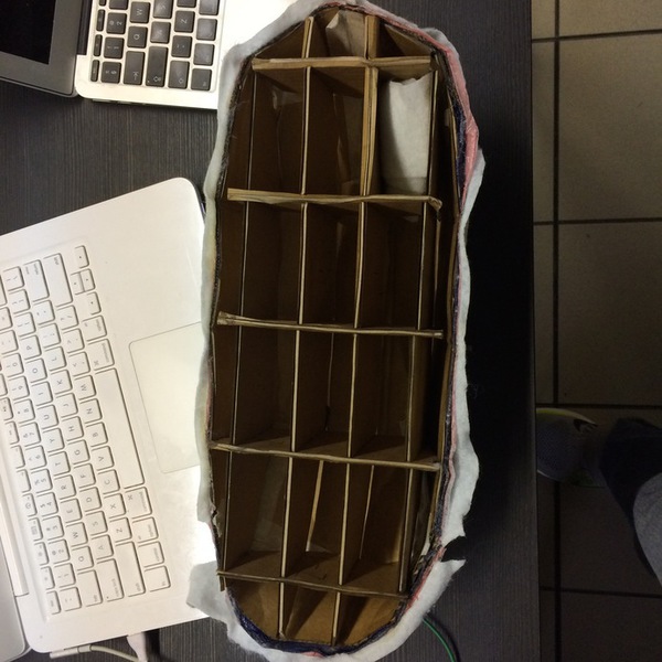
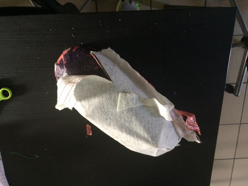
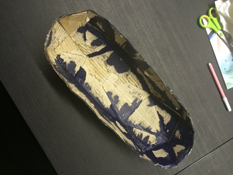
Removing the internal supports was a pure nightmare. The release worked on top of the glued seams, but the plane surface area stuck permantly to the cardboard interior. The final structure is solid and beautiful, but the inside is a nightmare.
Conclusions
The two burlap layer seems the best for strength to transparency balance. I will execute another round of the base and try again. The second try was a failure. The process was a lot clearer the second time trhu, but the support structure was not strong enough and the release does not work even when coated three times. Composites are tricky and complicated. This week's assignment took six weeks and was still a failure, but I have the feeling that with a few more tries I will be making something profound. I will do another piece in my Final Project.