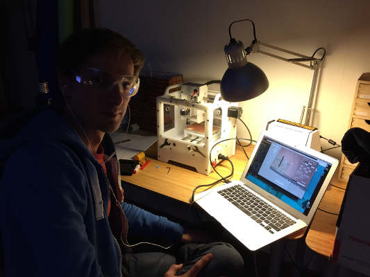
Electronics Production.
Make the FabISP in-circuit programmer.
Installing the local Fab module.
make sure you got all the dependencies installed
make clean
make fab
sudo make install
ls /dev/tty* (see if you have ttyUSB0. make sure the machine is connected)
sudo chmod 0666 /dev/ttyUSB0 (gives permission for Fab modules to write to the USB port)
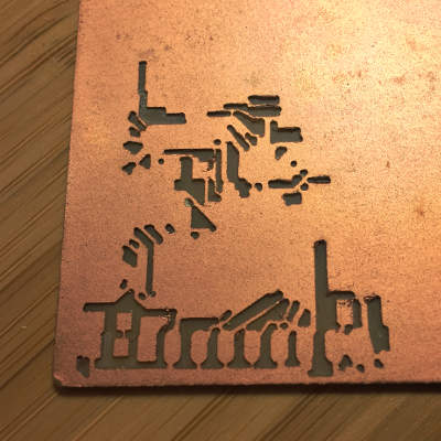
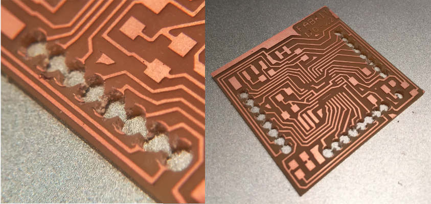
Milling the board
Milling the board seems straight forward since most of the settings comes with the Fab module so there are not as much testing back and forth as with the laser.
Roland MXD-20 mill, Bed size.
152,4mm x101.6mm
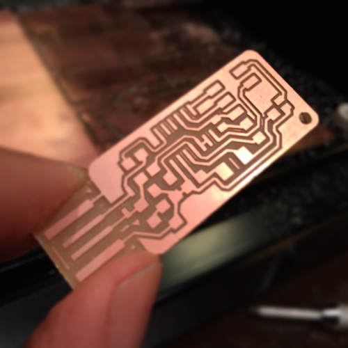 Fab ISP Andy version milled on Roland MXD-20
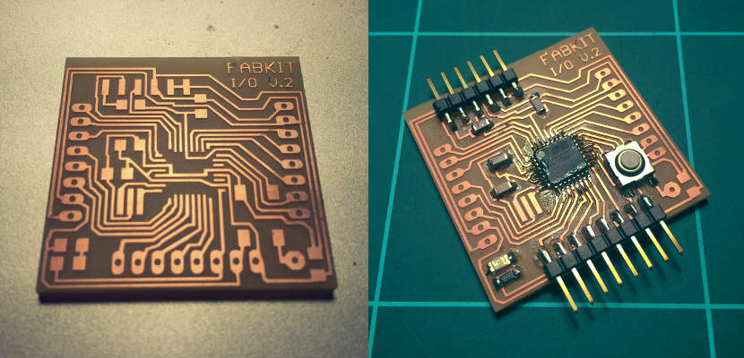
Stacking the board.
It was very confusing with the numbers so I did some research. Turns out that There are three systems that are used:
3 figure SMT resistor code system
As the name indicates this SMD resistor marking system uses three figures. The first two figures in the code indicate the significant figures, and the third is a multiplier. This is the same as the colored rings used for wired resistors, except that actual numbers are used instead of colors. Therefore an SMD resistor with the figures 472 would have a resistance of 47 x 102 ohms, or 4.7kΩ. However beware of resistors marked with figures such as 100. This is not 100 ohms, but it follows the scheme exactly and it is 10 x 100 or 10 x 1 = 10 Ω. Where resistance values less than ten ohms are used, the letter "R" is used to indicate the position of the decimal point. As an example, a resistor with the value 4R7 would be 4.7Ω.
4 figure SMT resistor code system
The four digit or four figure SMT resistor marking scheme is used for marking high tolerance SMD resistors. Its format is very similar to the three figure SMT resistor making scheme, but expanded to give the higher number of significant figures needed for higher tolerance resistors. In this coding scheme, the first three numbers will indicate the significant digits, and the fourth is the multiplier. Therefore an SMD resistor with the figures 4702 would have a resistance of 470 x 102 ohms, or 47kΩ.
EIA96 SMD resistor code system
The EIA SMD resistor coding scheme uses a three character code: the first 2 numbers indicate the 3 significant digits of the resistor value. The third character is a letter which indicates the multiplier. In this way this SMD resistor marking scheme will not be confused with the 3 figure markings scheme as the letters will differentiate it, although the letter R can be used in both systems. To generate the system the E-96 resistor series has been taken and each value or significant figure set has been numbered sequentially. As there are only 96 values in the E-96 series, only two figures are needed to number each value, and as a result this is a smart way of reducing the number of characters required.
Programming the board.
USB ports on macs have a fuse. I'm not sure if it is also implemented in Ubuntu so I booted up in mac and tested my board to see if I get a “draw to much power” warning, I did not! I'm good to go.
make clean
make hex
sudo make fuse
Here I got an error
So I opened the Makfile in the firmware and uncommented:
"AVRDUDE = avrdude -c usbtiny -p $(DEVICE) # edit this line for your programmer"
...and commented out:
"#AVRDUDE = avrdude -c avrisp2 -P usb -p $(DEVICE) # edit this line for your programmer"
I still got an error on install so I started inspecting the solders and go through the connections with multimeter and continues flow. I found one mistake!
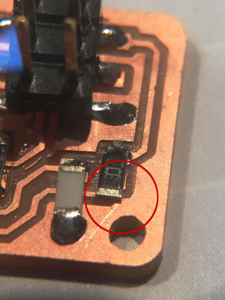
On one of the 0 resistor it was to long and short circuit to ground. I remove it and just made a solder ball connecting the two and started over:
make clean
make hex
sudo make fuse
sudo make program
...and it worked!
I desolder SJ1 and SJ2 and SJ3
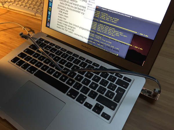
Booted up in mac again went to about this mac/ system settings/ USB and there it was fabISP Another victory!
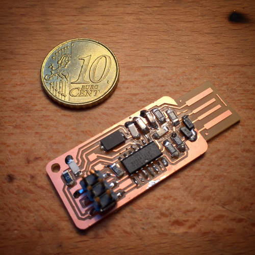
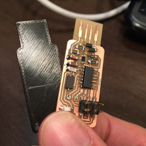 The finished board with a 3D printed bottom plate for a snug fit in the USB port
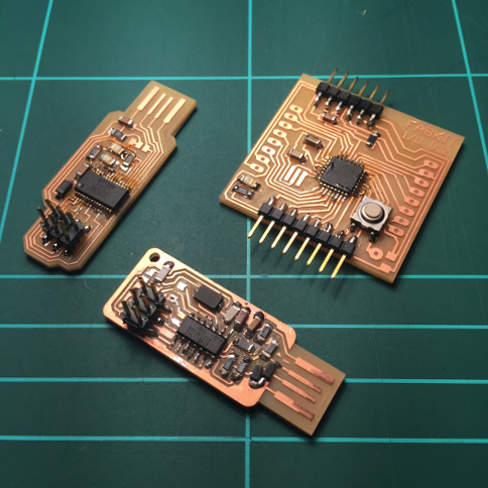
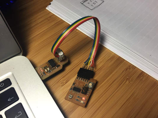
 Let the procreation begin!
FTDI board.
I went for a remake of Andrew Leeks FTDI Board (week 15, add the bottom of page) witch is a modification of SparkFun FTDI Basic Breakout - 5V
It uses a part that is not in the Fab inventory the Capacitor 10uF SMD
Soldering the was a bit of a challenge. The pins are really close. Here flux is your best friend. Going through it with the multimeter I had two pins always short circuiting. No matter what I did. After 4h without success I started looking at the schematic and board files only to realize that they where supposed to be connected.
Programming an ATtiny w/Arduino IDEtutorial
For some reason Arduino IDE 1.6.0 did not have right to write to the USB port on Ubuntu easy fix for this is to start Arduino IDE with "sudo sh arduino" in the arduino folder.
The other machine
I had some extra time and wanted to try out The Other Machine. After have played around with it for a couple of hours this is my verdict.
All in all I'm happy to go back to the Roland MXD-20.
Fabduino
Download Fabduino cut files.
The work flow was pretty straight forward. The Fabduino comes with 3 .png files. Trace, the dimension cut-out and holes. (holes being white on a black background in the downloaded image) As you can see the holes got way to big. The reason for this, and this is only my guess, is how the Fab module analyses the image. Invert the image would solve this black holes on white background... or there is a setting I don't know of.
How ever after have given it some thought, I came to the conclusion that it is better to have a flat board. So I skipped the hole milling completely.
My new family.