To library or not to library.
I started with my hello board (button + LED) from week 6 and Hal board from week 10 to see if I could get them talking using the FTDI Cable. I had to add a wire to the hall board for theTX line and then putting them all in a bread board for making the connections.
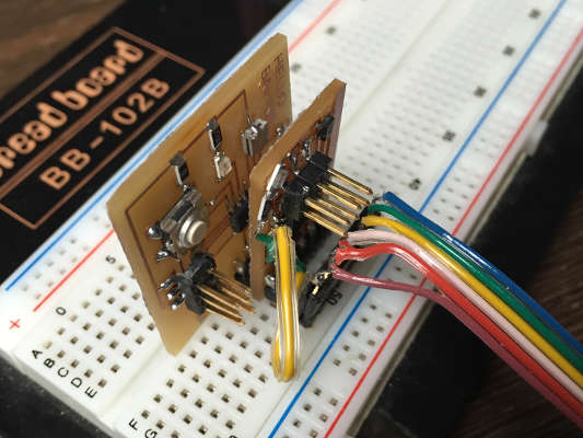
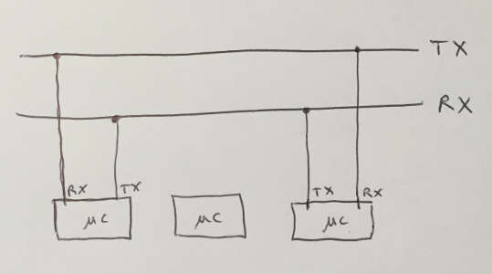
Since this is my first stab at "Networming" I had to refer back to the schematic of how RT TX connection work several times. One does not simply send character in all direction expecting it to get heard. The crossing of wires RX to TX did not make it more easy to wrap my head around it.
I could not get any characters printed out to the serial monitor... and Neils code where confusing. I had an idea of what was happening but to much where just assumptions.
So I tough I would make it simple and import a serial library. I followed Elliot Williams AVR Programming book and used his library and examples but the problem was that he was using An ATmega168 and I soon noticed I was missing some registers (UCSR0A) that he used. So a bit more research and found this link
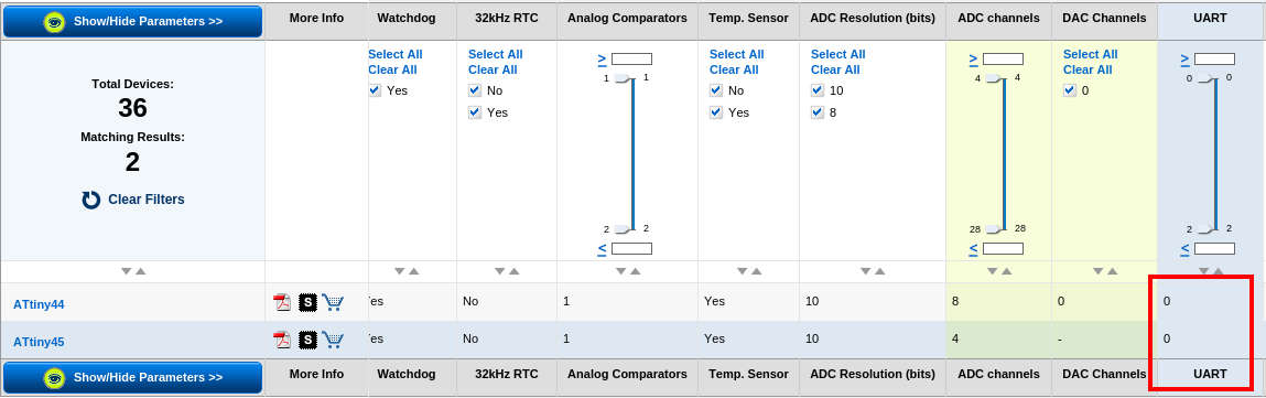 So ATtiny 45 and 44 don't have USART!?.
Back to Neils code and my HAL sensor I went. After a lot of monkeying around and some reading I could finally get my code to print out N or S depending on the direction of the magnet.
usart from Anders Haldin on Vimeo.
While loop conflict
I also tried to do a 'get_char' on my Hal board to blink the led but it would only run the main while loop once and then nothing. and My previously working N/S print out also stopped. I assume this happens because there is a while loop inside 'get_char' function that takes over from the ADC loop.
Button-Keyboard-Led
Since i could not get the 'get_char' to work on my Hal board I continued with my hello board. this time having a key stroke blinking a led and the button on my board printing out a character.
usart from Anders Haldin on Vimeo.
To make them talk to each other I have to make an echo board. But I was running out of time so that have to wait for now.
3 boards one day.
Now understanding Neils code it was easier to do the actual assignment but first the boards
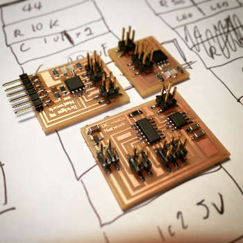
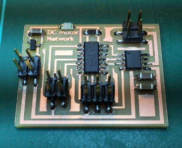
I decided to make Breakout board, LED board and a DC motor board and my plan was to design mill and stuff them all in one day! I managed but there where some design errors on the way...
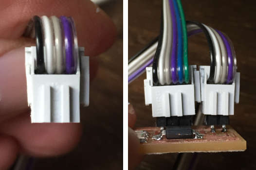
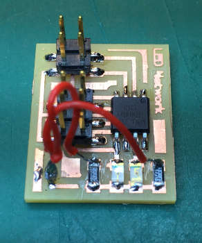
First mistake I noticed was that the header pins where to close! Mental note to self... Make sure there are enough space between the header pins ...MAKE SURE!
 Three happy stooges.
 I had to trim of a bit of the sides to get both to fit.
I could upload code to my ATtiny 44 with out a problem but both ATtiny 45 gave me a rc=-1 error! I had this error before in week 11... that time it was a missing ground wire... well what do you know I had forgotten to connect FTDI to ground, only to reset! And finally I had crossed some wires where the two LED/resistors where.
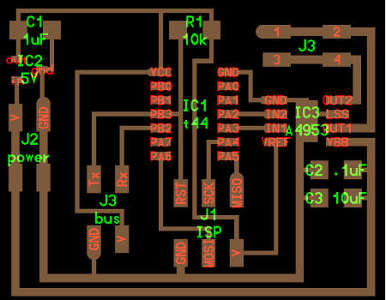
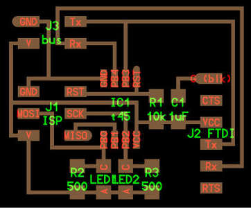 Bridge board first spiral
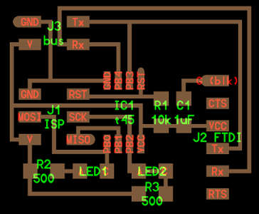
 Design error fix.
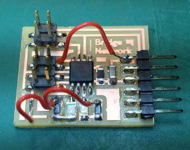
 Second spiral.
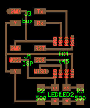 LED board first spiral
 Design error fix.
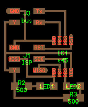 Second spiral.
 DC motor first spiral
 Design error fix.
 Second spiral.
I could print out to the serial port terminal form my bride board, but not from the LED board! I check my ports and pins but they all seemed fine. Then I remembered that I read somewhere on some previous student web page that they had to change the bit delay to make it work. So I changed #define bit_delay_time from 100 to 102 and it worked! Changing the node ID and trigger keys was the easy part after all my previous struggles with the code.
serialcommunication from Anders Haldin on Vimeo.
Where is the DC motor?
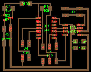
While I was working, having all boards connected to the bus, I suddenly saw a cloud of smoke in the corner of my eye. Something burned on my DC motor board! After some investigation we found the design error, it turned out that I (also) was feeding power through my voltage regulator from the opposite direction. I swapped out the burned voltage regulator and adding a diode to prevent further cloud generation. But the motor was still not running and when I check my PWM in the oscilloscope it is all gibberish...
DC Motor Debunk
In the C code I disabled all PWM code and just turned one pin high and the other low. This would have the motor spin continuously one way. I powered my board with a 5V adapter bu still nothing. So I started measuring voltage across the circuit. I could see that after the voltage regulator and the diode which was a LED at this point (cold not find any diodes when I was fixing my design error) was around 2.8V and on the output pin it was 3.558. I also measured the output pins on the Full-Bridge DMOS PWM Motor driver, they where both set at 5V. No wonder the motor did not move. I checked the data sheet and if I understand it correctly it has to get 2V/pin input, I had two pins so I was voltage short. I swapped the LED for a diode and this gave me more power to the micro controller but not enough. So I cut the wire on a 12V adapter and solder a female pin connector to it and I now got 4.23V. I plugged the motor in and it was working!
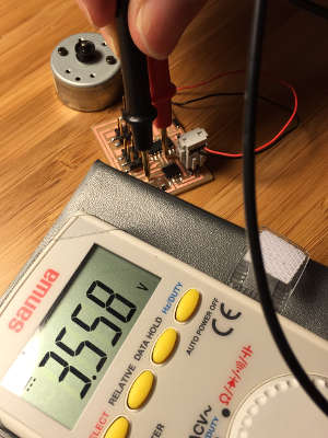 Powering it with a 5V adapter.
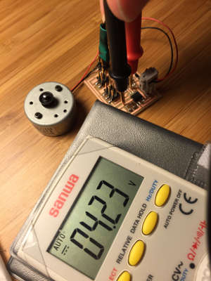 Powering it with a 12V adapter.
In short the problem was a combination of low power source and voltage drop on the LED not giving enough power for the motor driver to switch the pins.