Charlieplexing - Binary Watch
For charlieplexing I just wanted to do a simple board with 6 LED so I can easily grasp the concepts and programming part but then the classic, and so dangerous, feature creep happened. Some how I ended up making a binary wrist watch... so of to Kokopelli and start coding.
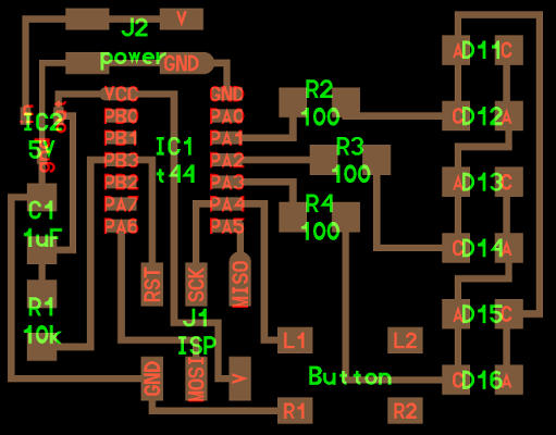
I used Neils hello.array.44.cad as a starting point. But re-arranging the LED was not as simple as I first thought it to be. After some hard work and a lot of cross referencing (thanks Francisco) I got it all placed out. I added a battery and a switch for it so I can cut the power connection when programming it. I also added a Button to be able to set the time.
Kokopelli have no pads for the battery or the switch I was using, but since this is a one time use (I hope) i did not take the time to custom make them. So eye balling it first placing traces where I wanted the battery but what I first did not realize was how big the 3V battery is compared to the other components... almost as big as 3 buttons! So a quick .png export to gimp for control measuring the pad size and back to Kokopelli and redesign. In the end I want to have the battery covering the resonator to save space but thought that this first prototype should have easy access.
48 components later.
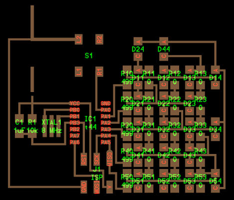 Can you spot the errors in the design?
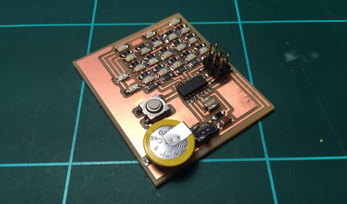 Adding all the components took some time, but was not to difficult.
Programming.
Loading the Make file I got a:
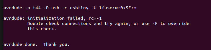
Internet recommend the following solution:
"Error 1" for "avrdude: initialization failed, rc=-1 Double check connections and try again" is one of the most common problems you will encounter when trying to send the program to the board. This can happen most certainly because of a hardware problem, so:
- check that you have un-soldered the 0-resistors from the ISP board
- check that you installed the right FTDI drivers (OS version and 64 bits)
- check that the rainbow cable is well pressed and not connected backwards!
- check that the FTDI cable has ground (black) connected to ground in your board
- check Eagle schematic and Fab modules tool path against your board for milling errors
- check for soldering errors and loose legs
- check the board with a multimeter for discontinuities
I made sure the cable was all the way to the bottom and they where not, could hear a small click as it settled. Tried again and now the fuse was a success, but the celebration came to a abrupt stop when I tried uploading the the C code and got the same rc=-1 error again.
Next step was to swap micro controller but that made no difference so I tried changing the programming cable and now it worked every second time.
Then Francisco "Eagle Eye" Sanchez came by and noticed that I had forgotten the ground wire for the resonator, and guess what... I could upload code! I turned the switch to power the board with battery and... nothing happened... until i pressed the button. Very dim lights as probably because I followed Neils schematic where he is powering it with 5 V and I am powering it with a 3V battery. So back to the soldering station.
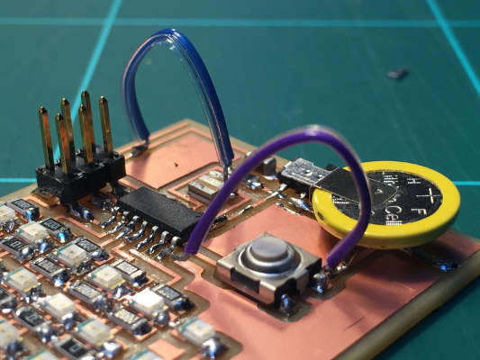 Wire jumpers for fast modification to a broken design.
Changing from 499 to 100 ohm resistors made the LED glow brighter but why did I have to press the button to get it to work!? Some further investigation revealed that I had forgot the ground connection for the micro controller.
Binary Watch Fail from Anders Haldin on Vimeo.
Some of the LED don't light up, not sure if it is the code that have to be modified or my rearranging of LED that broke it?
Binary Watch bug solved!
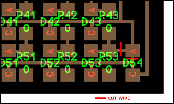
I came back to this board in week 15 trying to fix it. After some serious debugging, comparing and voltage meter action I finally found the error. Had two extra wires coming out from D54 that should not bee there.
 Wire jumpers for fast modification to a broken design.
Charlie 2
Working backward through the spiral development cycle I decided to simplify and make a simple charleplexing board. I did not feel I really understood the connections by modifying Neils board so this time I would make one with only 6 LED and a button. The goal being to end up with a code breaker puzzle board. Kind of like a low tech one button blip game.
Having sat down, drawing out the schematics and the wiring on paper I finally understood how charliplexing works. From there it went quite quickly to build the board, stuff it and program it.
 Reduced complexity to grasp concept of charliplexing
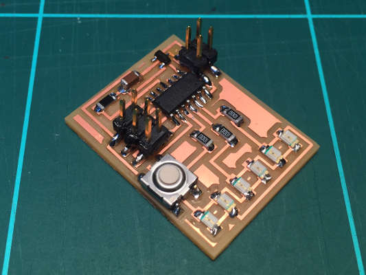 Final result after milling and stuffing.
The Code: Simple Charlie.
Simple charlieplexing from Anders Haldin on Vimeo.
Servos and PWM
Continuous Rotation Servo & Fixed Angle Servo.
The shape for my Servo board where determined by what material was left on the PSC plate. Form those dimensions I design the board in Kokopelli.
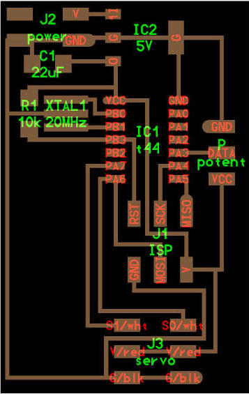 Designe form Kokopelli.
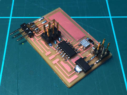 Final result after milling and stuffing.
Programming
I stared with a SpringRC SM-S4303R Continuous Rotation Servo The default rest point is at 1.5 ms pulses. Pulse widths above the rest point result in counterclockwise rotation, with speed increasing as the pulse width increases; pulse widths below the rest point result in clockwise rotation, with speed increasing as the pulse width decreases. I monkeyed around with the numbers until I found a mid point and an approximation of the the two extremes.
But the numbers did not add up so I check my PWM with an oscilloscope. My pulse width where double the length 40 ms so something off with the clock. I burned the boothloader through Arduino IDE. This changed it my pulses to 16 ms not 20 ms! ...so the timings are still off some how!
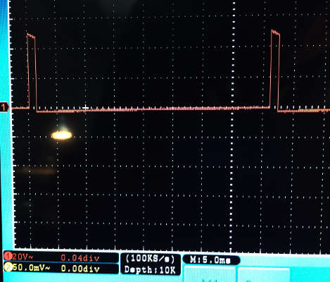 Oscilloscope shows a 40 ms between pulses .
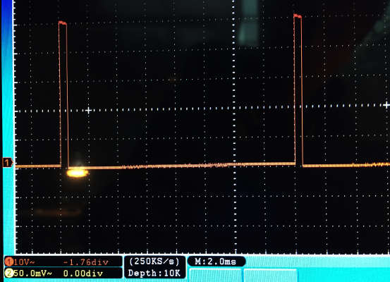 After burning bootloader it shows 16 ms..
Next I switch to TowerPro SG-5010, a fixed angle servo and with the same code but some adjustments I got my center and the two 180 positions with.
Showing the five PWM steps runing on the microcontroller..
fixedangle servo from Anders Haldin on Vimeo.